In my last post, I installed a phone holder on my tractor, which is very convenient but I wanted a way to charge it while in the holder. So in this post I install a combination USB charger and voltmeter to kill two birds with one stone.
After searching Amazon for the many choices of automotive USB charger sockets, I settled on this Yonhan model. It operates on 12 to 24 volts. It has two quick charge 3.0 USB ports. The total power output is 36W, or 18W per port. And one of my favorite features is the blue LED voltmeter that let’s me keep an eye on the health of my tractor’s battery. It’s described as Waterproof but there is no IP rating given. The body is made of aluminum alloy with the face and nut made of PVC. It’s just over 2″ deep and 1.13″ W. The included cable is 23.7″ long. It is certified by UL, CE & ROHS. The current price on Amazon as of the release of this video is $13.99. However, there are many makes and models to choose from so shop around to see which one has the features you are looking for.
Note: Links to Amazon products are Amazon Associate links that won’t cost you any extra, but will help support my efforts with a small commission on qualified products. Thanks for your support!

The unit comes in a small, unassuming brown box and contains the charger itself, and the cable with inline 10A fuse, which I won’t use and you’ll see why further down in the post. The rubber lid has a window to see the voltmeter and tabs that seal the UBS ports.

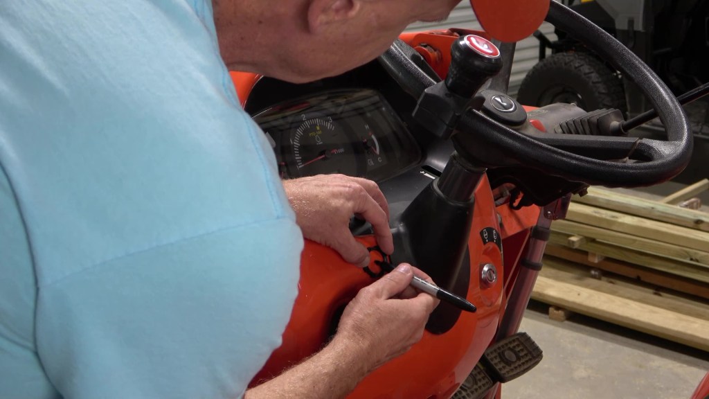
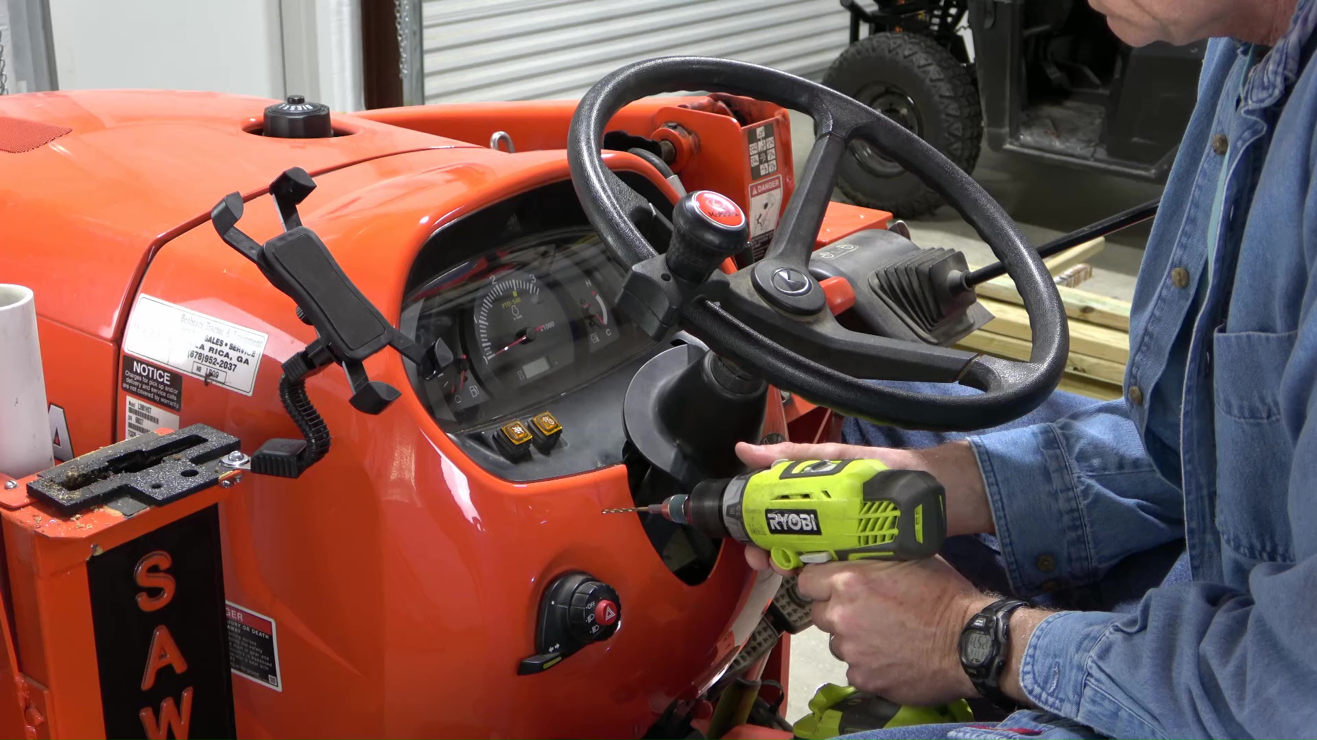
First, I use the nut from the charger and a Sharpie marker to mark where to drill. BTW, I already checked to make sure there is enough room behind the hole to mount the charger. I found out by removing the steering column boot and checking with my hand. I start by making a pilot hole with a small bit. Then I use a 1 1/8″ hole saw to finish the hole.


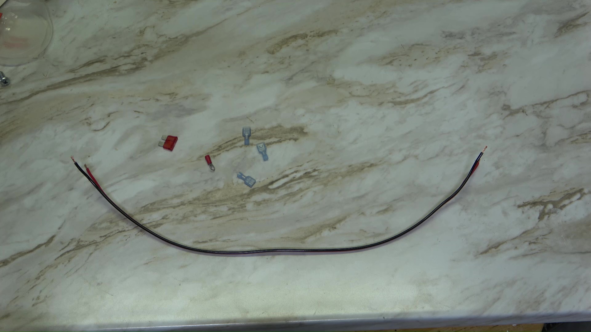
My wiring harness is made from a 22″ length of two conductor 16 GA wire I bought on Amazon. To make it up, I’ll use three spade connectors. And one ring connector. And I have a 10 Amp blade fuse for my auxiliary fuse box. I crimp two spade connectors to the end of the cable that will connect to the charger. On the fuse box end, I crimp a spade connector to the red positive wire. Followed by a ring connector for the black negative wire.
The positive and negative terminals on the charger are marked and the positive terminal is brass colored. I connect my wiring harness accordingly, with the positive wire to the brass terminal and the negative wire to the other.


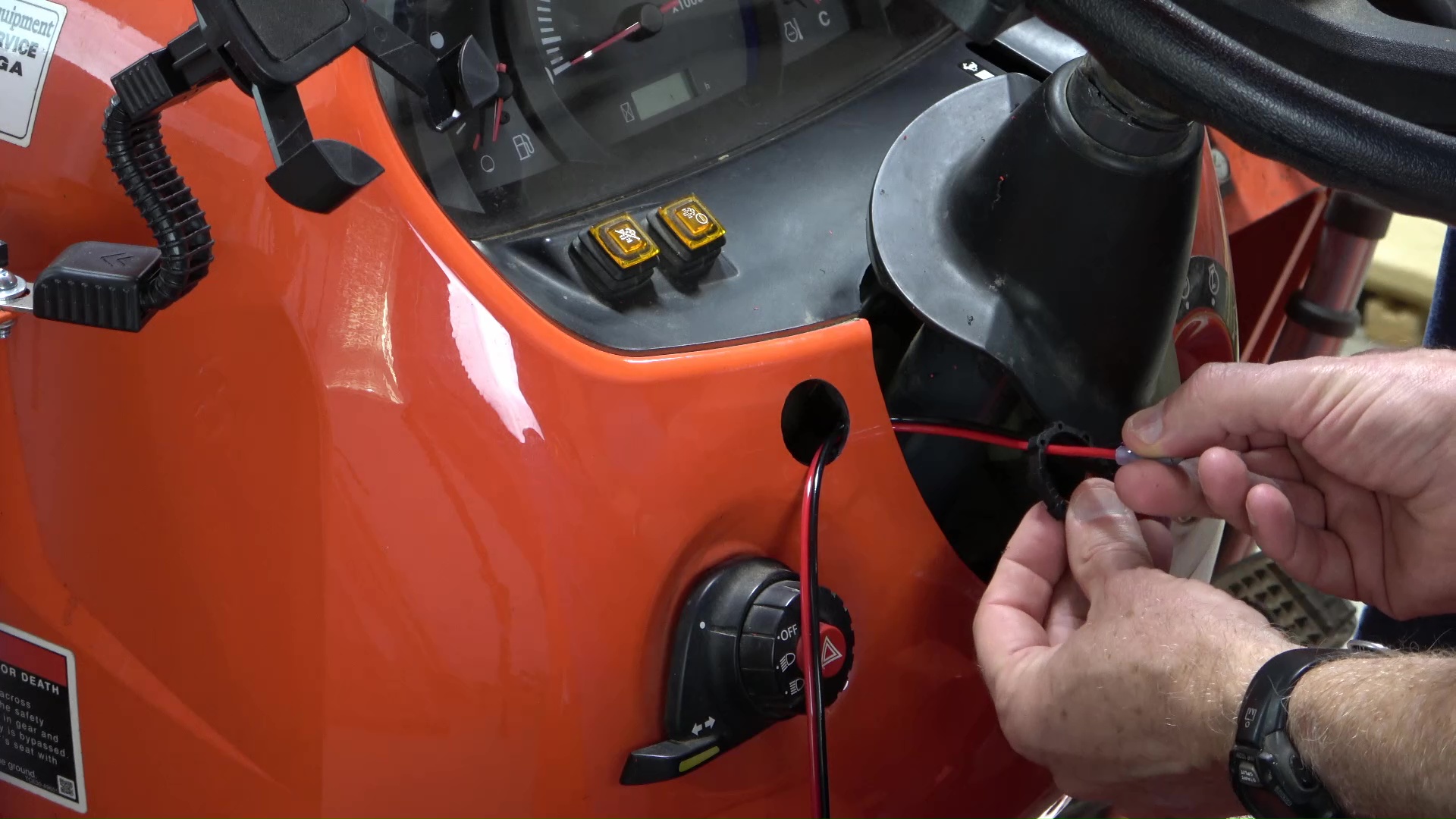
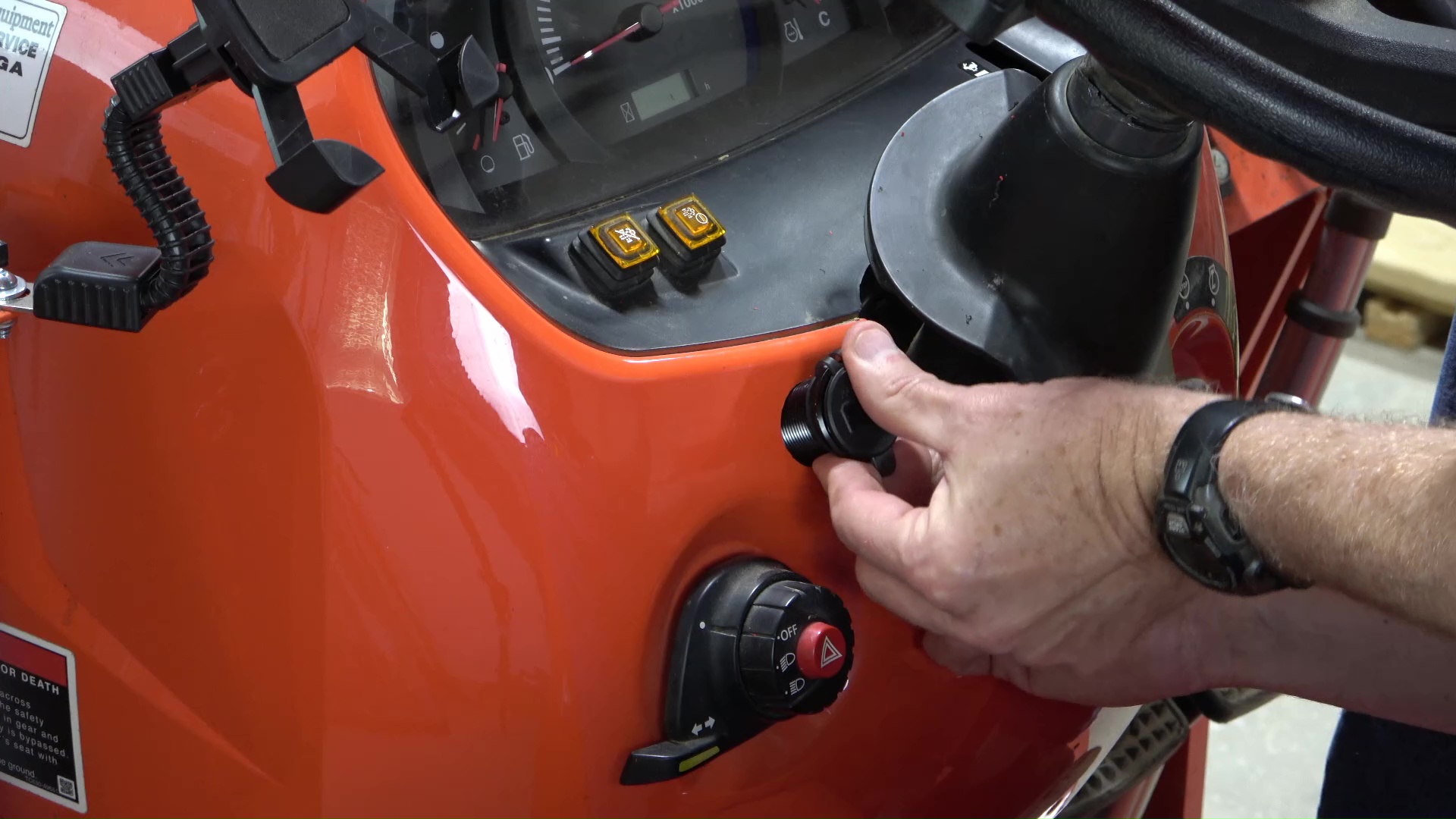
I put the fuse box end of the harness through the hole. Slip the nut over the harness from the back side. Then feed the harness through the hole and the nut. I push the charger in the hole then tighten the nut,
then put the steering column boot back on.

Next, it’s time to connect the harness to my auxiliary fuse block. The ground lug is where the negative ring connector will attach. The positive spade connector will connect at the fuse number 4 output terminal.
I remove the nut and lock washer from the ground lug. Put the ring connector on. Then put the lock washer and nut back on and tighten it up. I remove the fuse block cover. Connect the positive spade connector to the output terminal. Then I insert the 10 Amp fuse and put the cover back on.


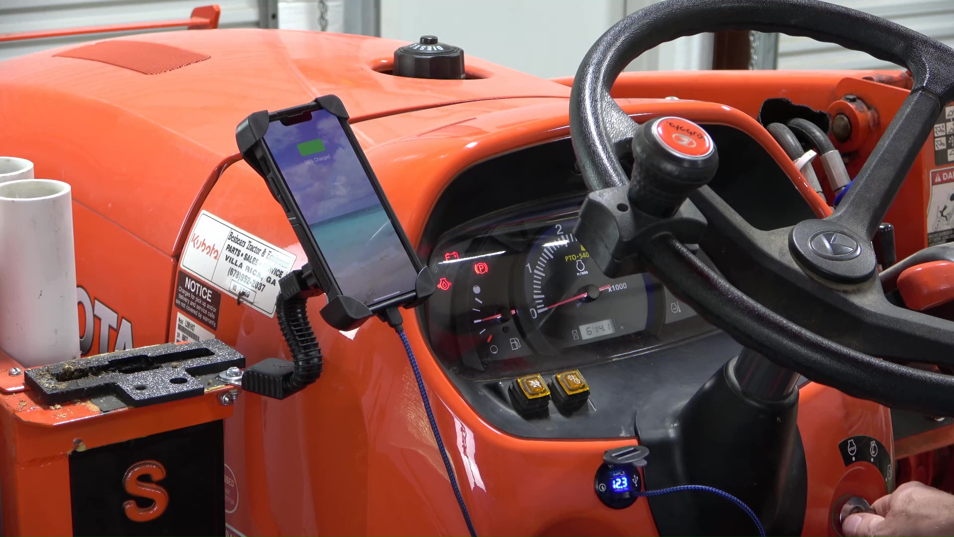
When I turn the key to the first position, the voltmeter reads 11.8V, which is low to begin with and falls to 8V while cranking. That’s a good indication that I may need to replace the battery soon. It slowly climbs to over 14V.
I test the UBS charging ports and both work. Great!