
I have wanted to add a chainsaw scabbard to my tractor for a while now, but my chain boxes took the most convenient spots for one. So here is how I added a chainsaw scabbard AND a couple of tool holders on a removable frame.
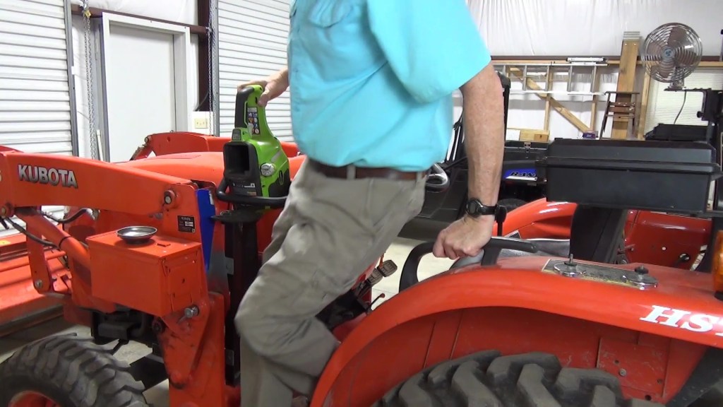
I chose to mount the scabbard and tool holder on the loader side frame. However, I could have mounted it on the loader main frame as well. Since I always have the loader on the tractor except for maintenance, I went with the side frame.


I’ll share all the measurements as I go but bear in mind that these only apply to a Kubota LA525 loader on a standard L series tractor, that is, the L2501, L3301 and L3901. Of course, the dimensions will vary from tractor and loader makes and models, but I’ll show you how I come up with the optimal dimensions for my tractor and you can use the same techniques on yours. Also, keep in mind that materials I used were based on what I had on hand and aren’t carved in stone.
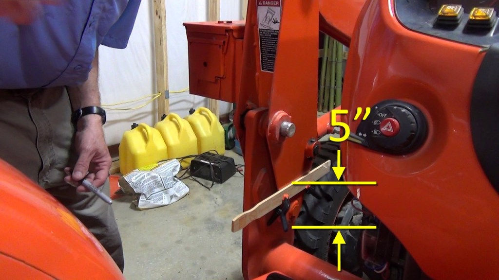
I began by drawing a level line on the lower section of the side frame 5″ from the bottom of the side frame. This is where the top of the first mounting bar will be welded. A paint stirring stick, clamps and a magnetic level make this easy.
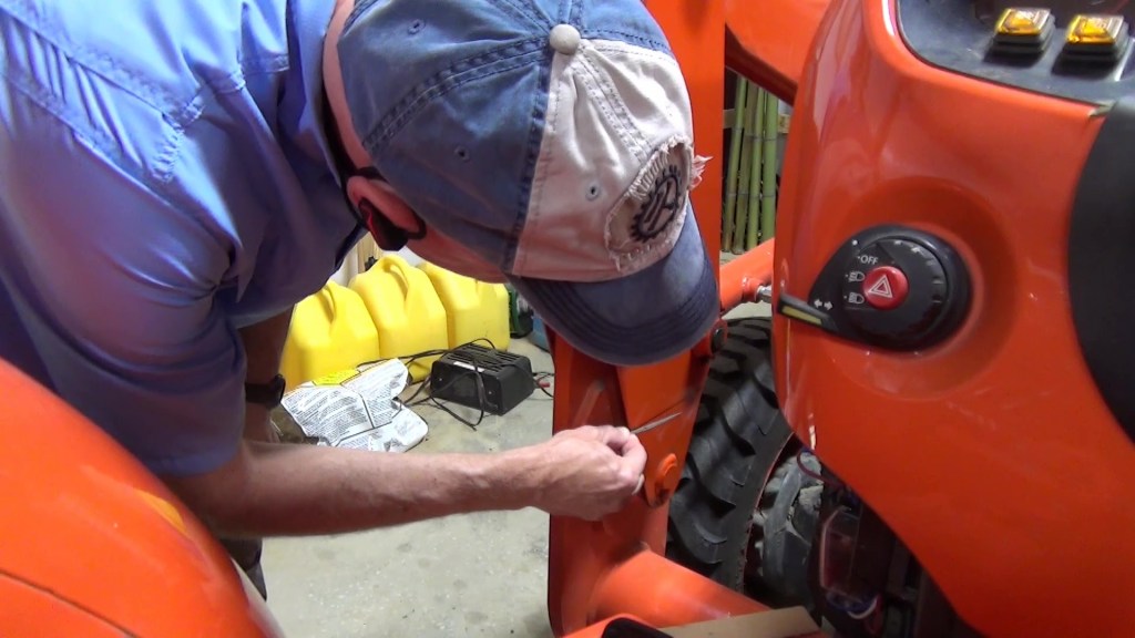
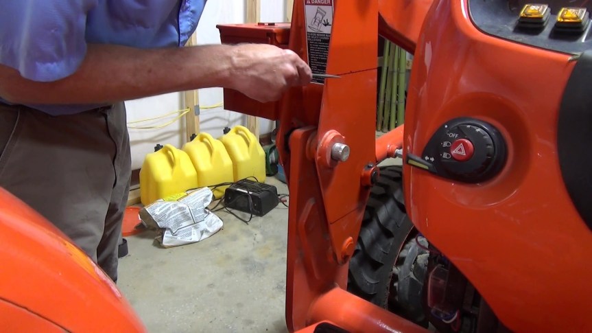
Next, I used a knife edge file to make some grooves in the side frame at both ends of the line I made. I did this because the lines would probably be gone when I removed the paint from the areas to be welded but the line will be useful for alignment purposes until then.
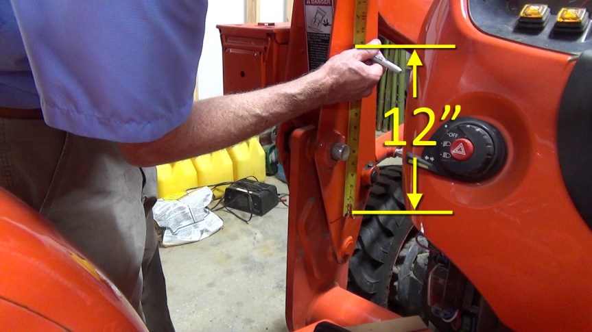
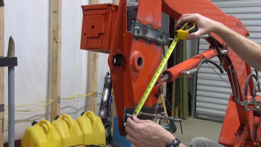
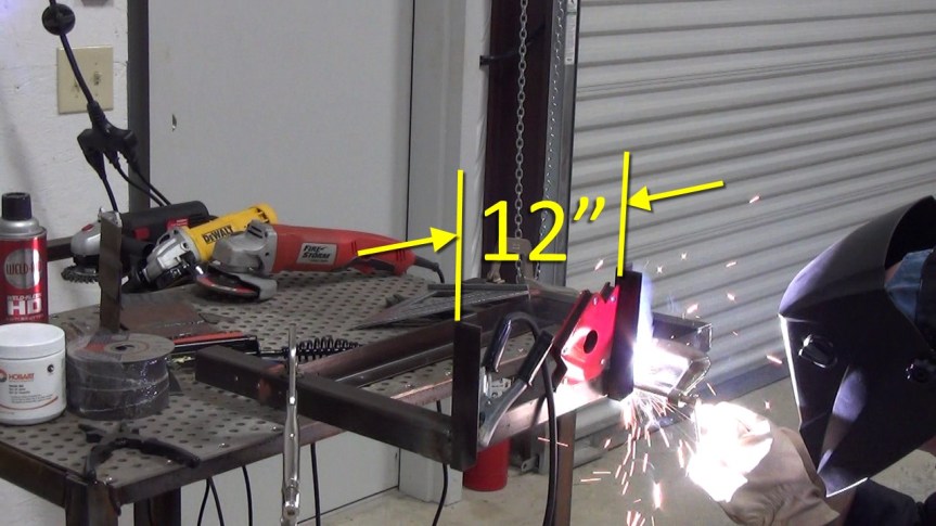
Then I measured 12″ up from the bottom line and made a mark for the top line. I clamped the paint stick below the mark and made sure the line was level before drawing the line. Again, I filed grooves at each end of the line.
I clamped a straight piece of 2×4 to the loader main frame as a reference for where the ends of the mounting bars will come to with respect to the edges of the side frame. So the end of the bottom mounting bar will be 2 ¾” from the side frame edge. And the top mounting bar will be 1 and 1/8″ from the side frame edge.

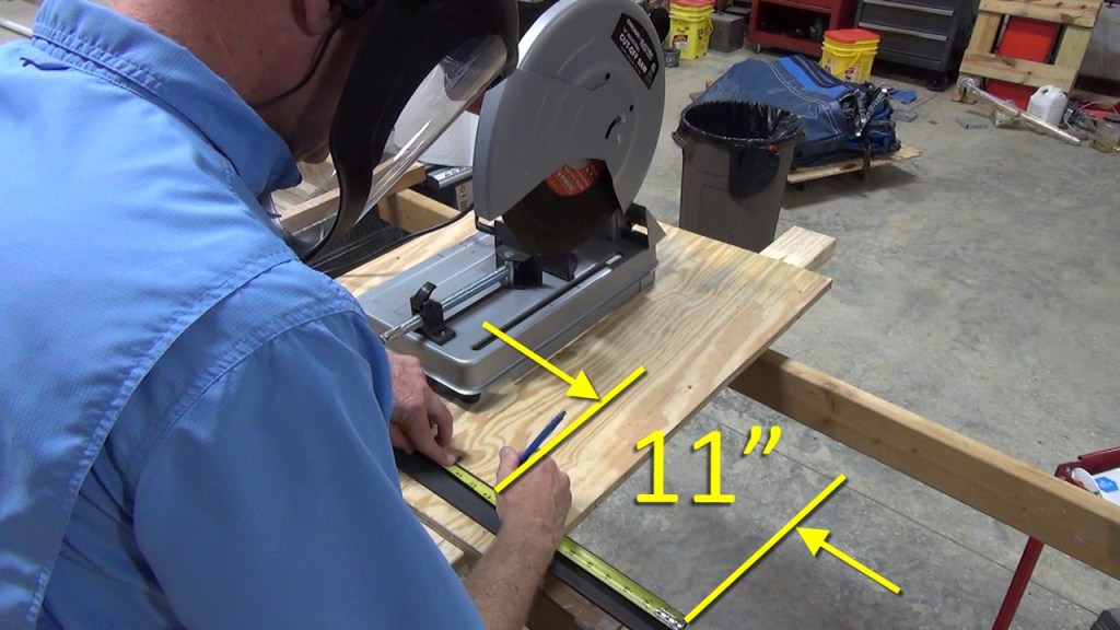
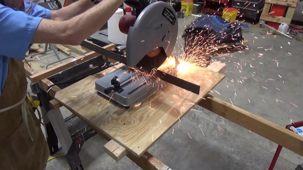
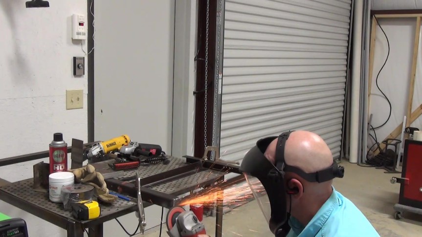
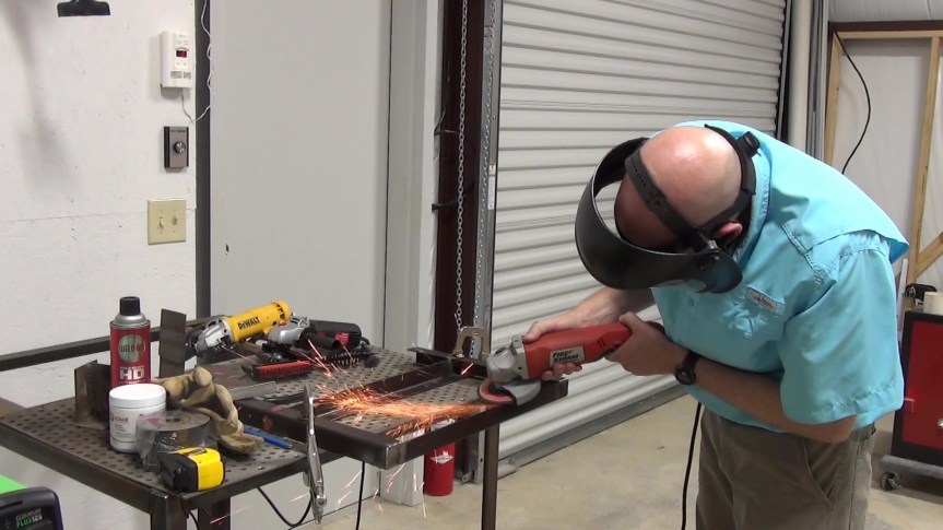
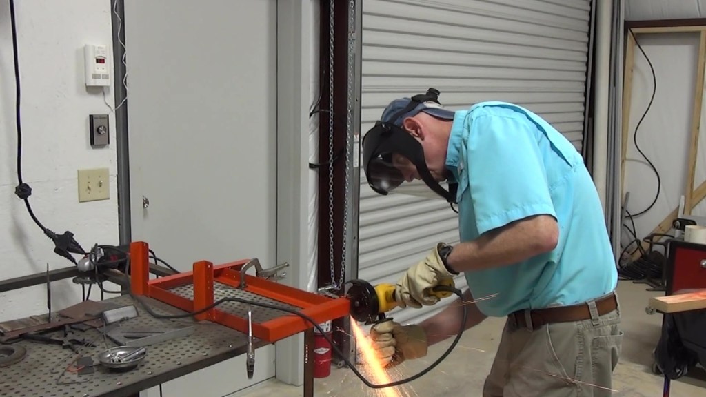
Next, I cut two pieces of 3/16″ thick by 2″ wide flat bar, 11″ long. Then I smoothed the rough edges off with an angle grinder.
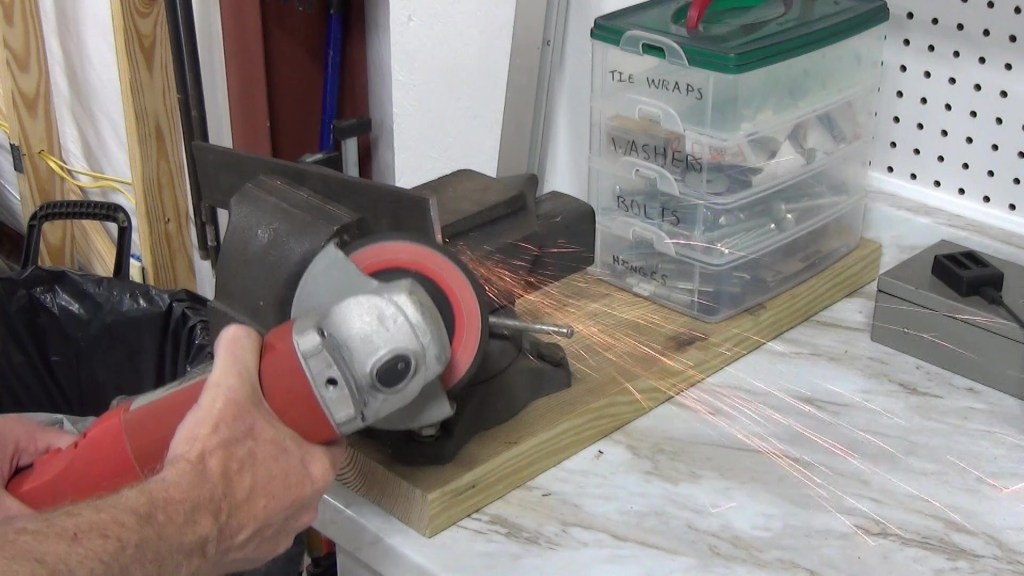
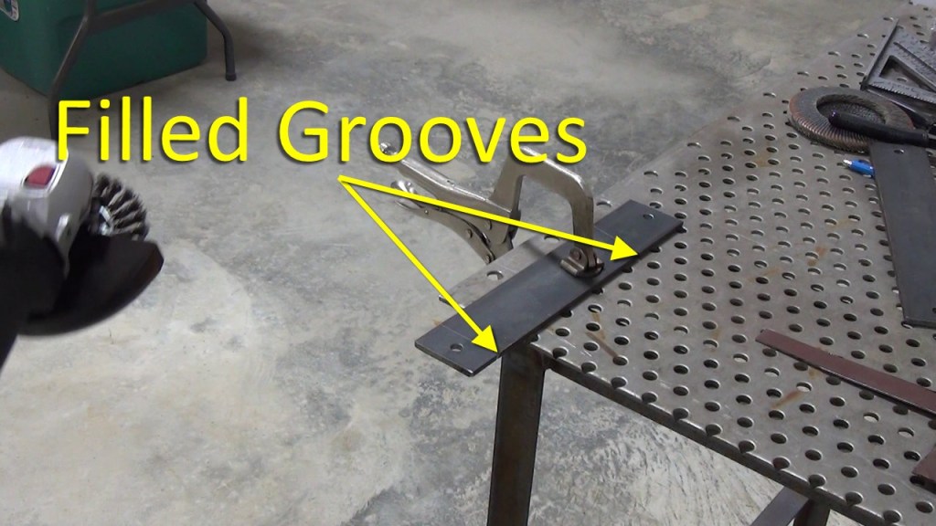
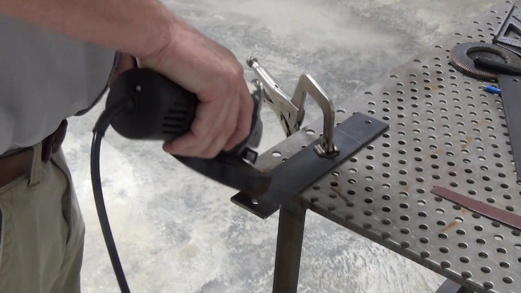
After drilling two 5/16″ holes 5/8″ from the end of each mounting bar, I removed the mill scale with an angle grinder and wire brush wheel. But first, notice in the slides below that I marked where the edges of the side frame will be on each mounting bar and I also filed grooves in the top edge of the mounting bars where they meet the side frame edges.

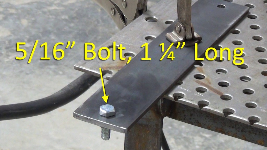
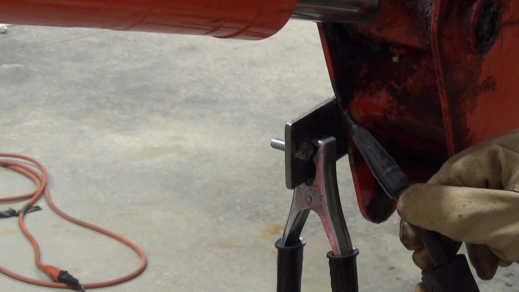
Then I welded 1 ¼” long 5/16″ bolts into each hole. BTW, I ground the zinc plating off on the 3 sides of the bolt heads before welding.
I put a nut on to hold the bolt in place until I was done welding.
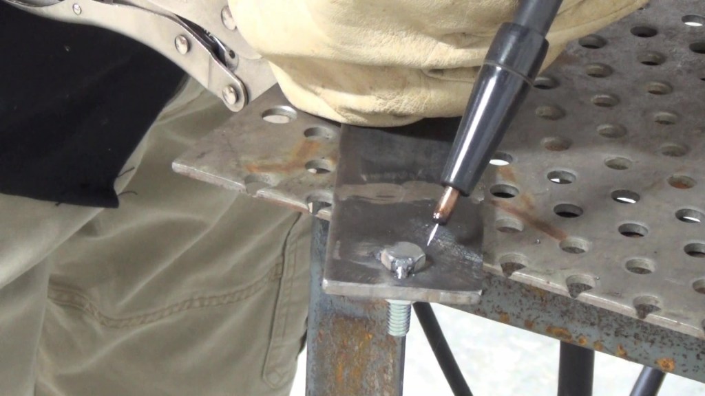
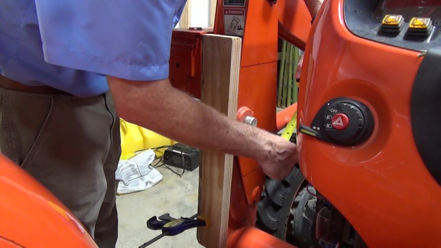
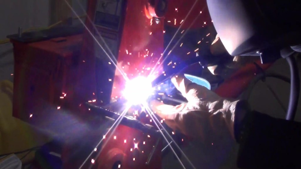
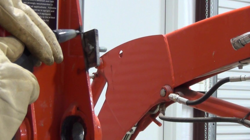
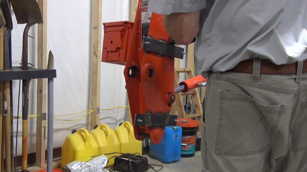
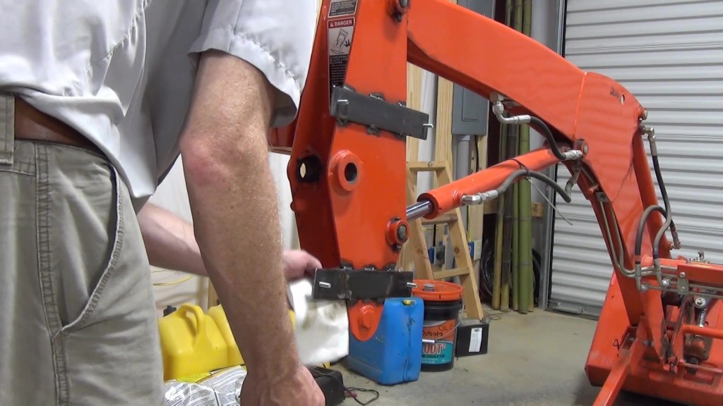
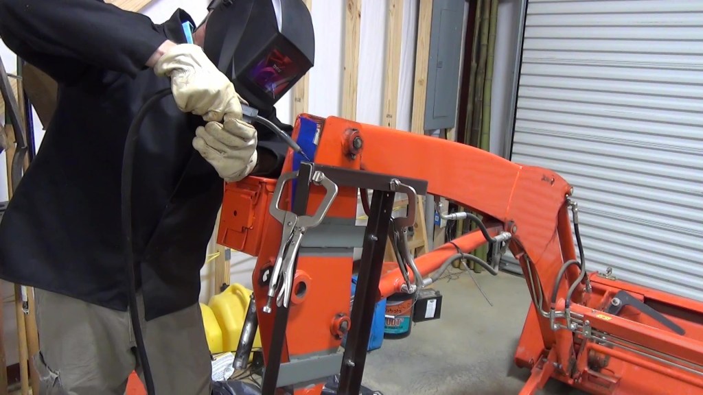
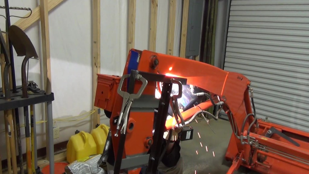
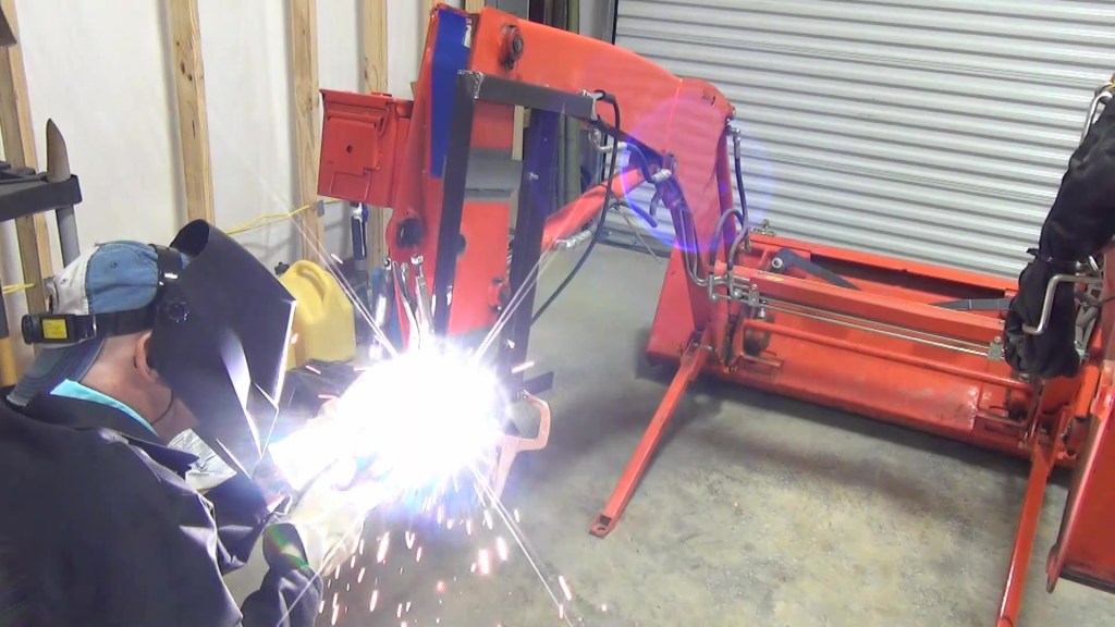
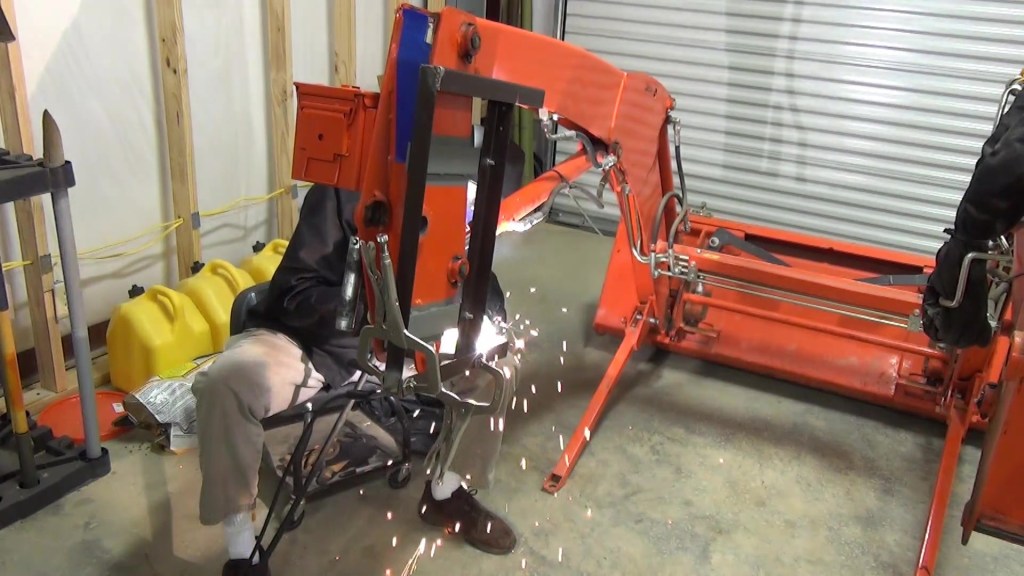
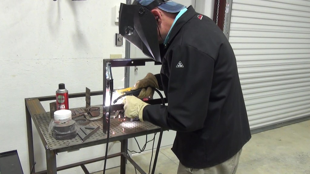
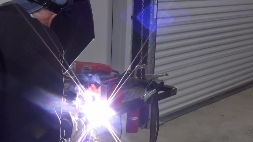
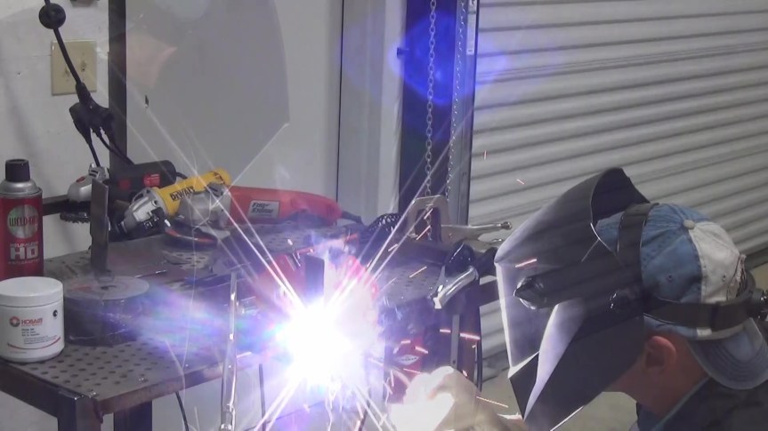
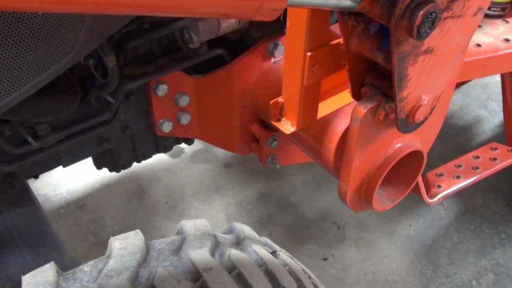
I removed the loader for easier access the work area and I ground the paint away from the areas to be welded. Then I clamped the mounting bars in place and started welding. I certainly didn’t need a continuous bead. These few spots were more than enough to hold the weight of my chainsaw and a few tools.
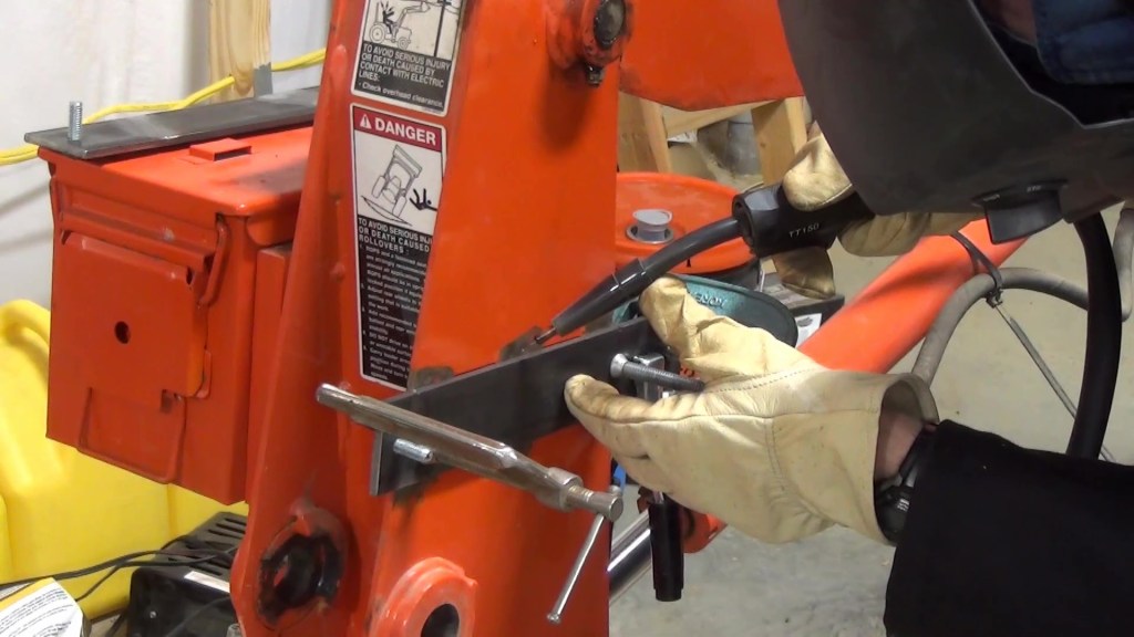
Before I welded the bottom mounting bar, I checked the measurements and checked for square.
I did a little welding on the backsides of each mounting bar for good measure.

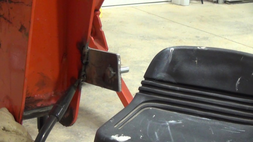


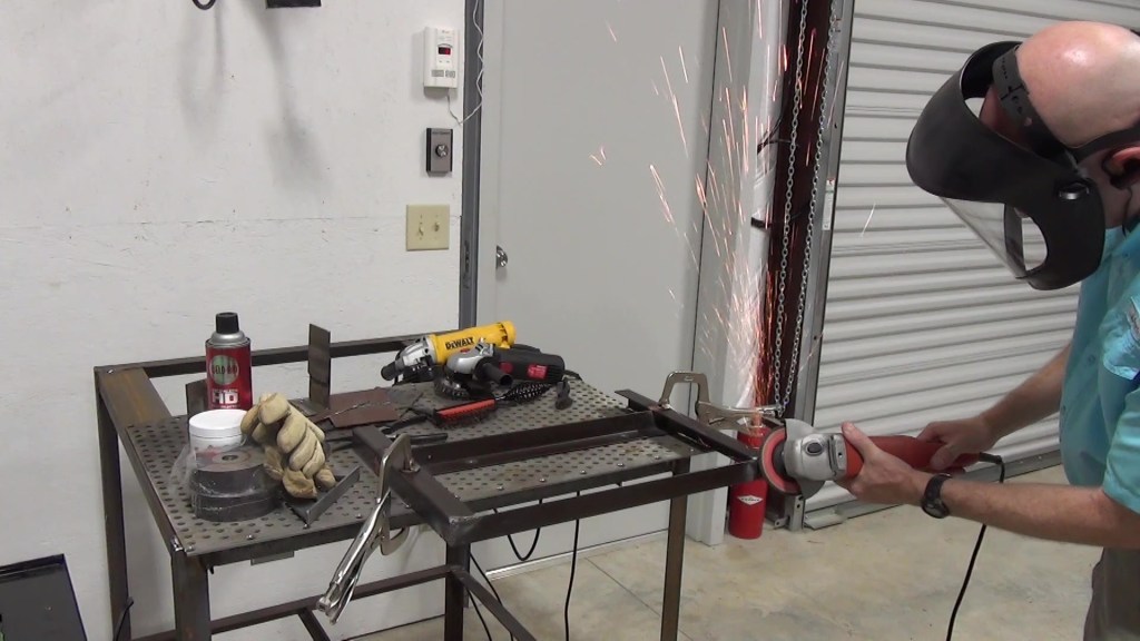
After that, I cleaned it all up, first with some grinding, then wiped it with mineral spirits and masked it off to put a coat of primer on the mounting bars. I top coated it with Kubota orange paint later.
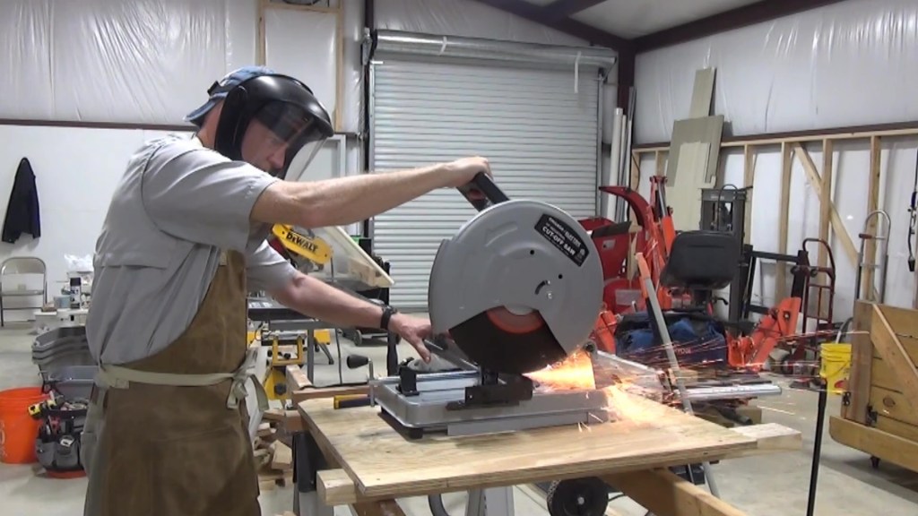
Now it was time to build the removable scabbard and tool carrier, which I made out of a set of bed rails we had in storage. They are essentially 1.5″ x 1.5″ angle iron, 1/8″ thick. Perfect for this project.
First, I cut the claw hook end off. The first two pieces I cut were the vertical supports, 22″ long. Then I drilled two 3/8″ holes, one 4″ from the bottom of the uprights and one 16″ from the bottom. I did the same for the other upright, only on the opposite angle side.
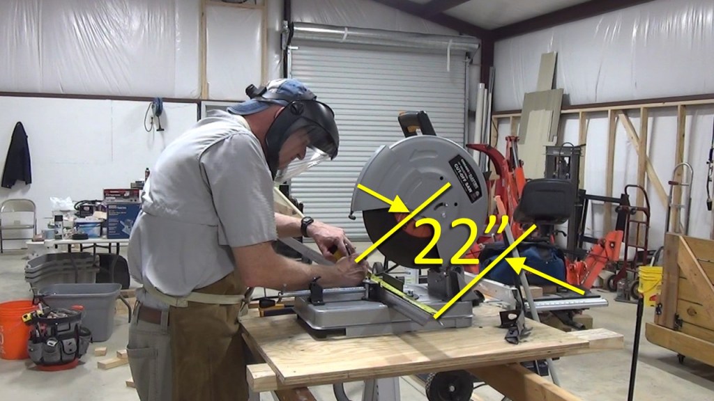
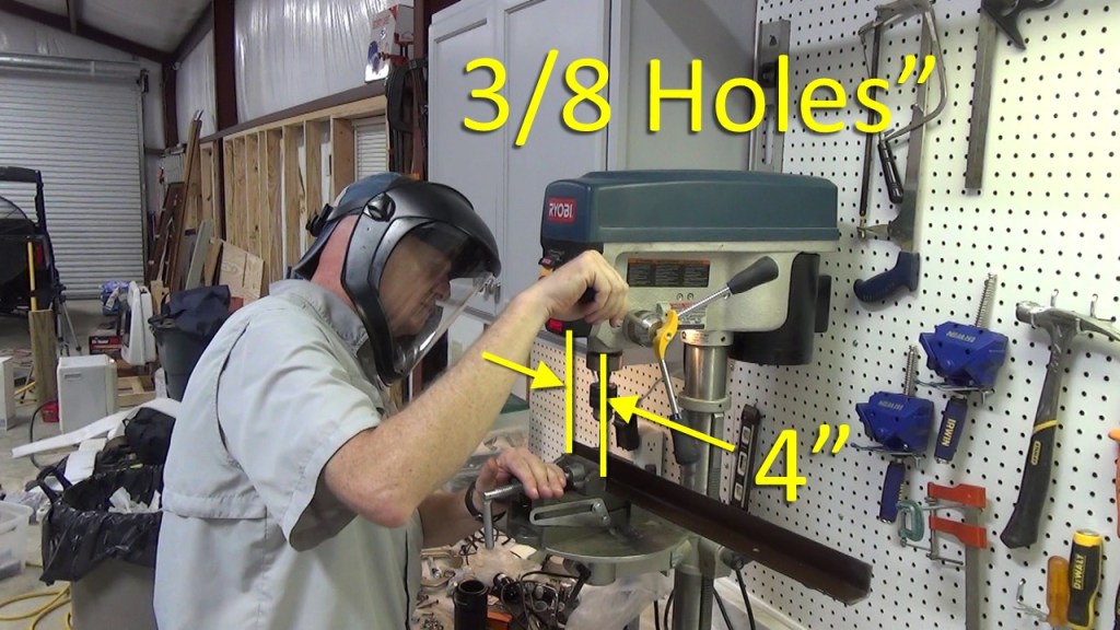

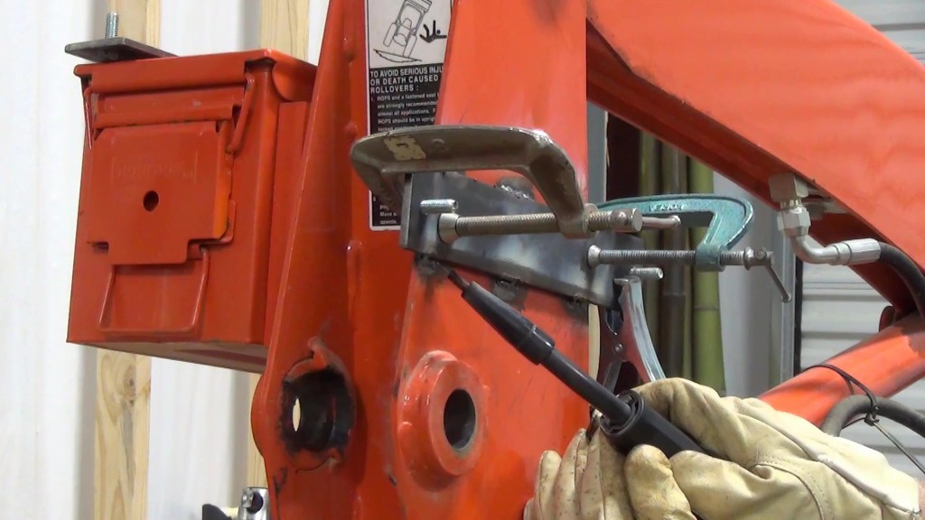
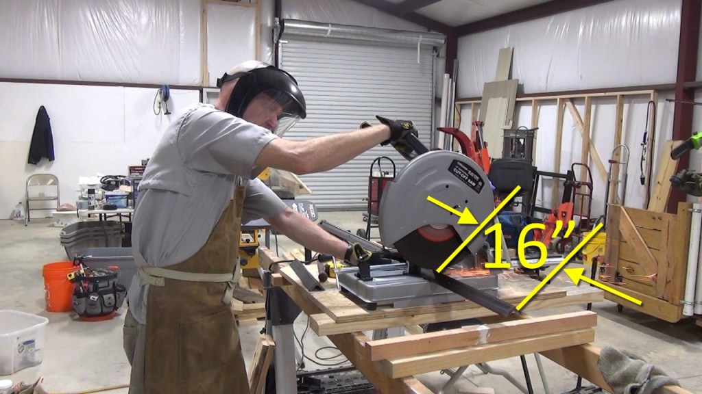
Next, I cut two horizontal supports, 16″ long. I temporarily mounted the uprights to the mounting bars so that I could test fit the horizontal supports. For clarity, the slides below also show the hole measurements again, one 4″ from the bottom of the uprights and one 16″ from the bottom.


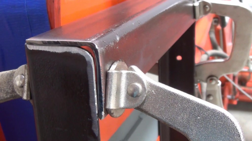
Here is the upper support clamped in place. Notice I have ground the edges with a bevel for the weld bead to live.
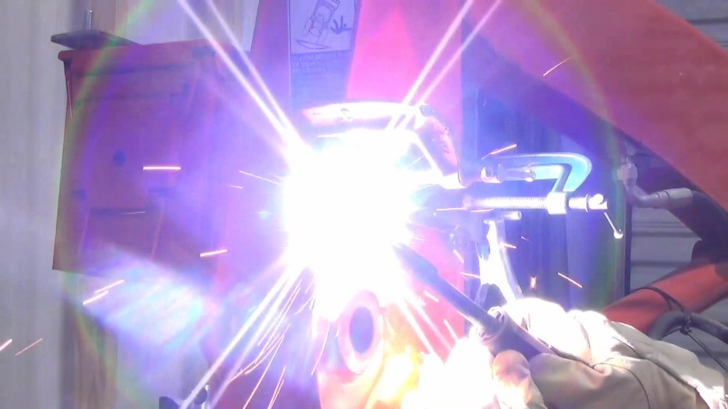
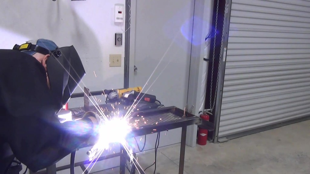
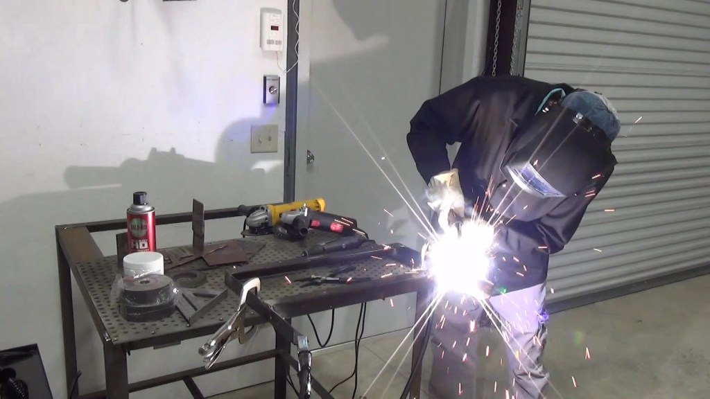
I welded the horizontal supports to the vertical supports.

Then took the frame to the bench to finish the welds and clean and grind them smooth.

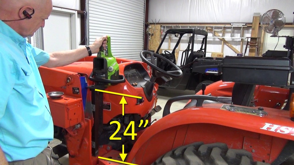
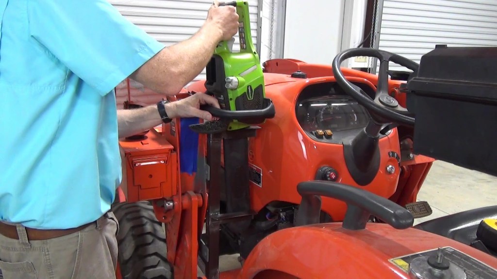
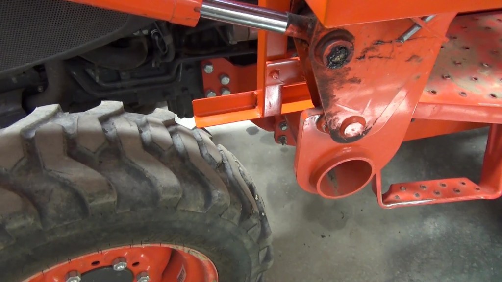
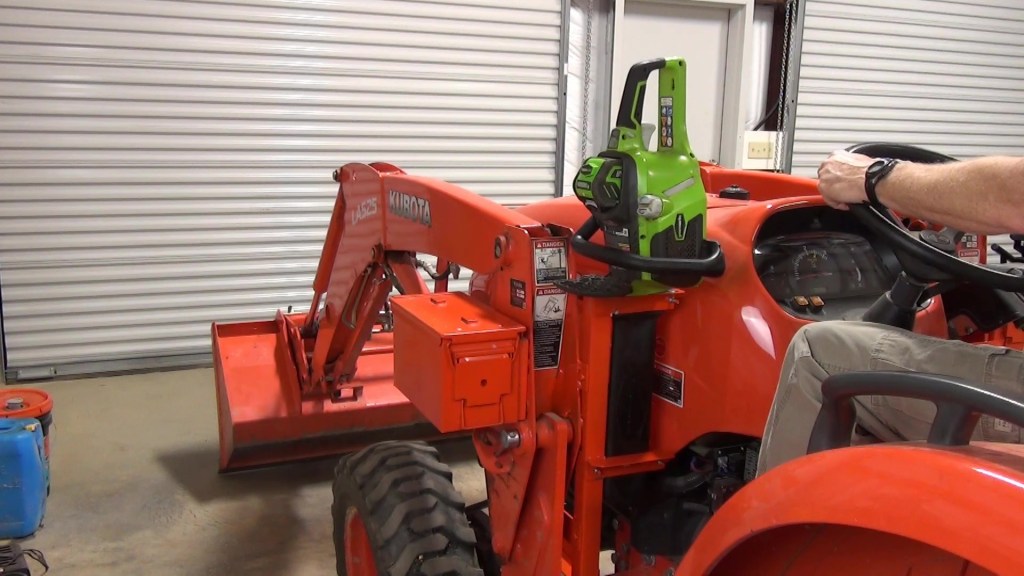
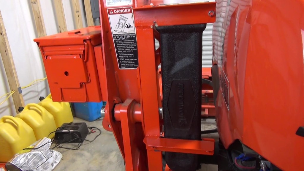
Next, I put the frame back on the loader and experimented with where to position the scabbard. Since I had a chainbox mounted to the side frame of the loader, I couldn’t mount a scabbard there. So I had to mount mine to the inside of the loader tower. My scabbard is 16″ but there is room for scabbards as long as 24″ to the floor of the deck. I positioned it so that it doesn’t get in the way of getting on and off the tractor.

I prepped the areas on the frame that the scabbard supports would go and cut a couple of notches where the lower scabbard support would be. Then ground the area of the welds.


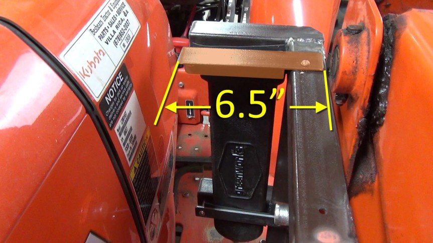
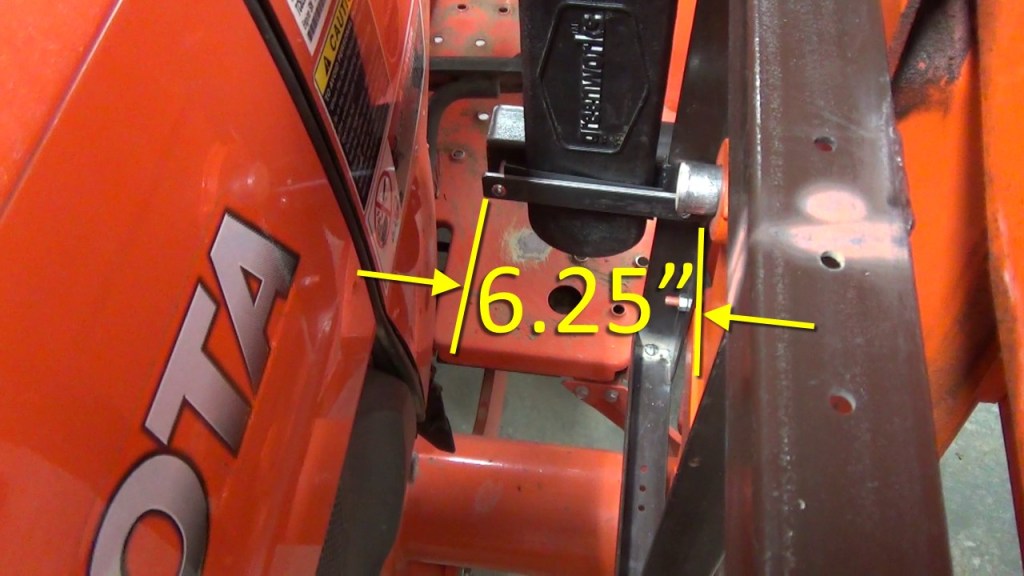
The two scabbard supports are 6.5″ pieces of bed rail with the corners clipped at 45 degrees so as not to be a hazard when I’m getting on and off the tractor. They are set 12″ apart.


After welding the supports on, I test fitted the frame and scabbard supports.
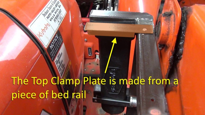
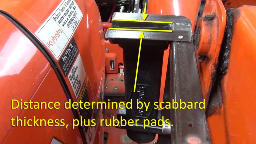
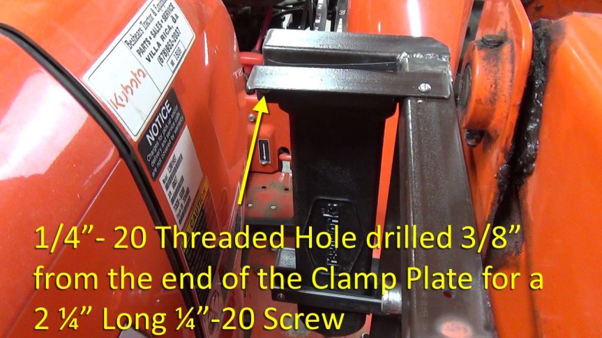
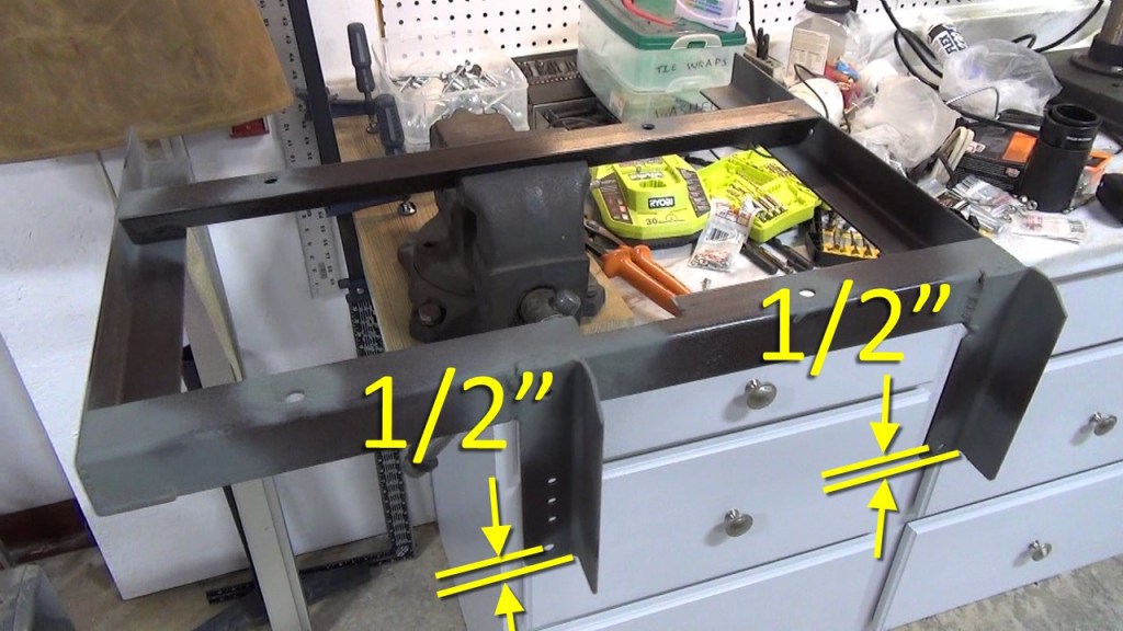
Next, I made the clamp plates that would hold the scabbard in place. The top one is a piece of bed rail and is 6.5″ long. It is held to the frame with a #10-24 machine screw and lock washer. The distance between scabbard support and the clamp face is determined by your scabbard thickness, plus a bit more for the rubber pads that will be glued on later. Oh, and the piece is notched 1.5″ to create the mounting tab for the screw. Also, a ¼”-20 threaded hole is drilled 3/8″ from the end of the clamp plate to hold the ¼” screw that puts the squeeze on the scabbard.

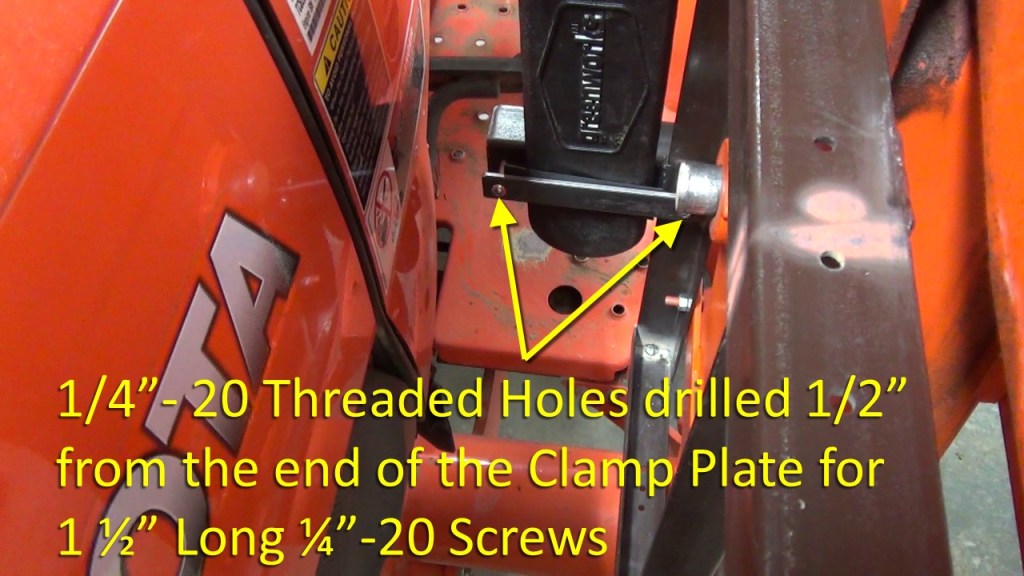
The bottom clamp plate is made from a piece of 1/8″ flat bar 1″ wide. It is 6 ¼” long. Two ¼”-20 threaded holes are drilled 1/2″ from the end of the clamp plate to hold the ¼” clamp screws.

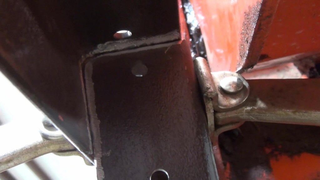
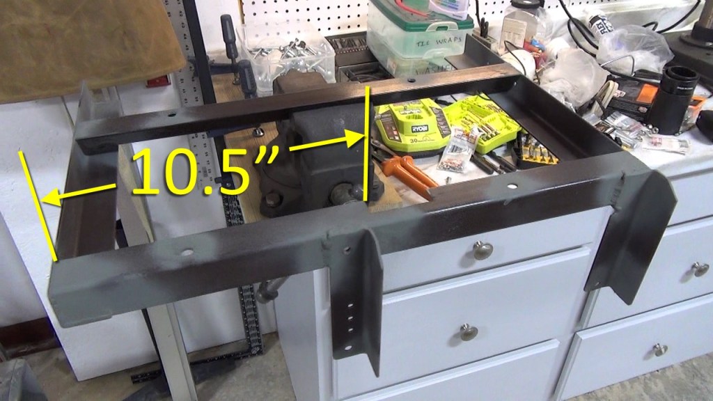
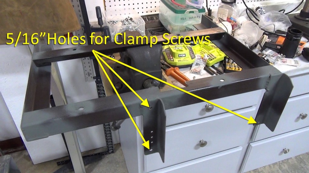
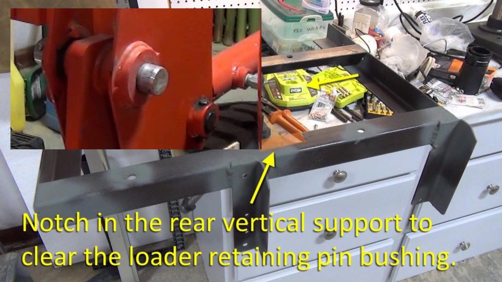
BTW, I had to make a notch in the rear vertical support to clear the loader retaining pin bushing. It is 2.5 long by 1″ deep, and 10.5″ from the bottom of the vertical support. The slides below also include a look at the position of the 5/16″ holes drilled for the clamp screws to go through. Notice that I have primed the areas of the welds to be ready for a top coat of Kubota orange paint.


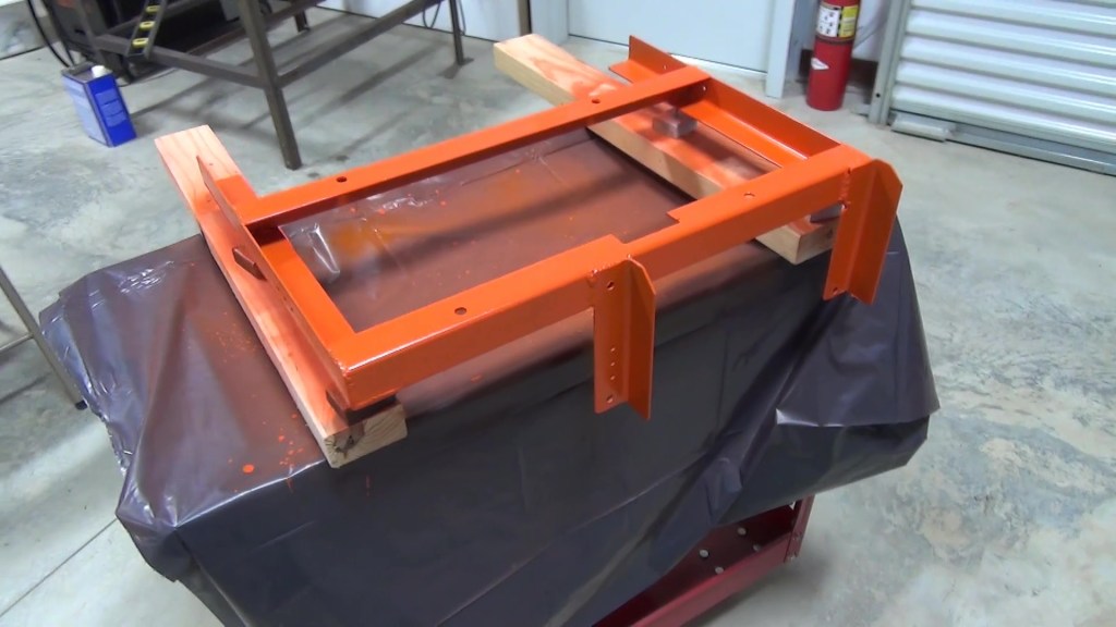
Speaking of which, here’s a look at the pieces after painting.

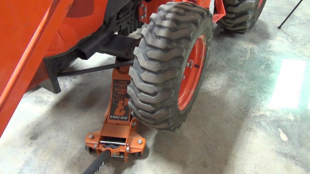
Along the way it occurred to me that I should make sure the left front tire won’t bind against the frame if the front axle is tilted up on that side. So I jacked it up and turned the steering wheel left. Sure enough, the tire hits the bottom horizontal support. So I had to cut it shorter and repaint the end of it.
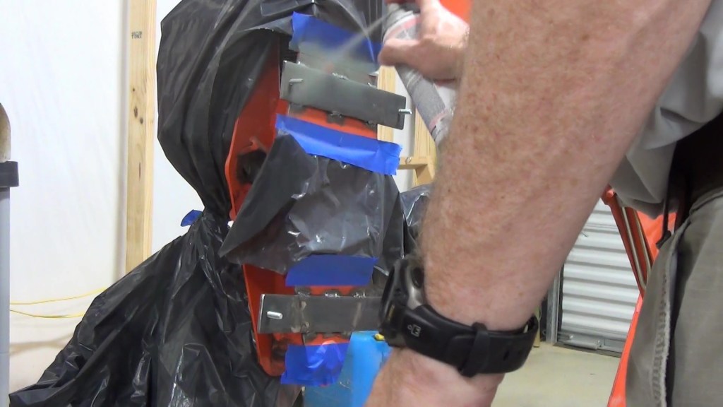
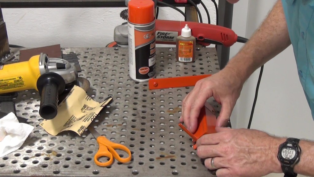
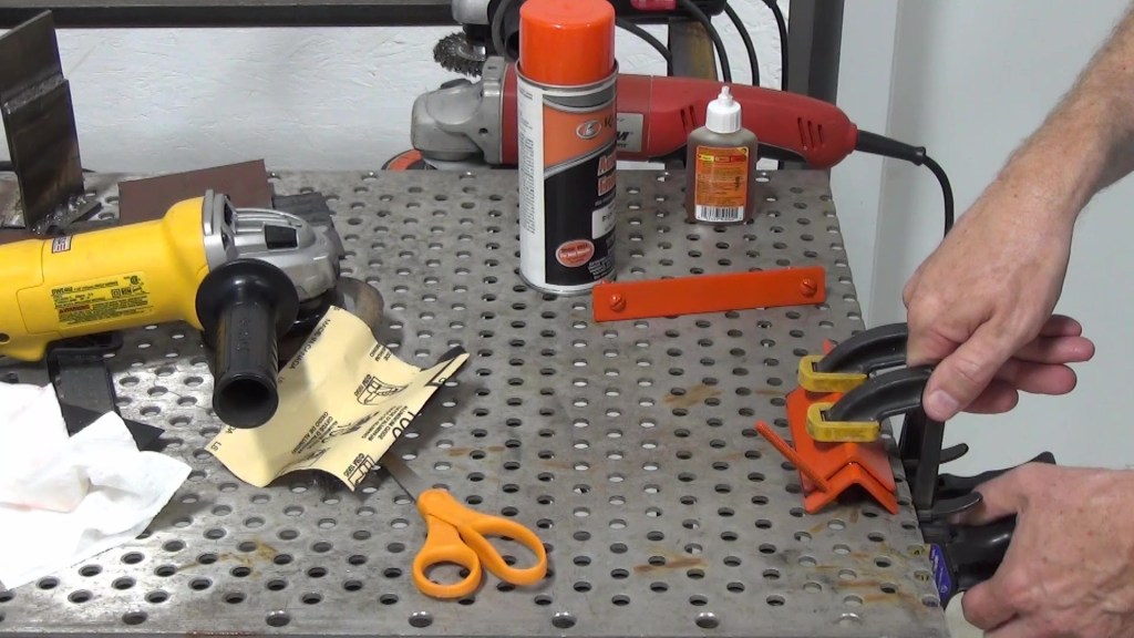
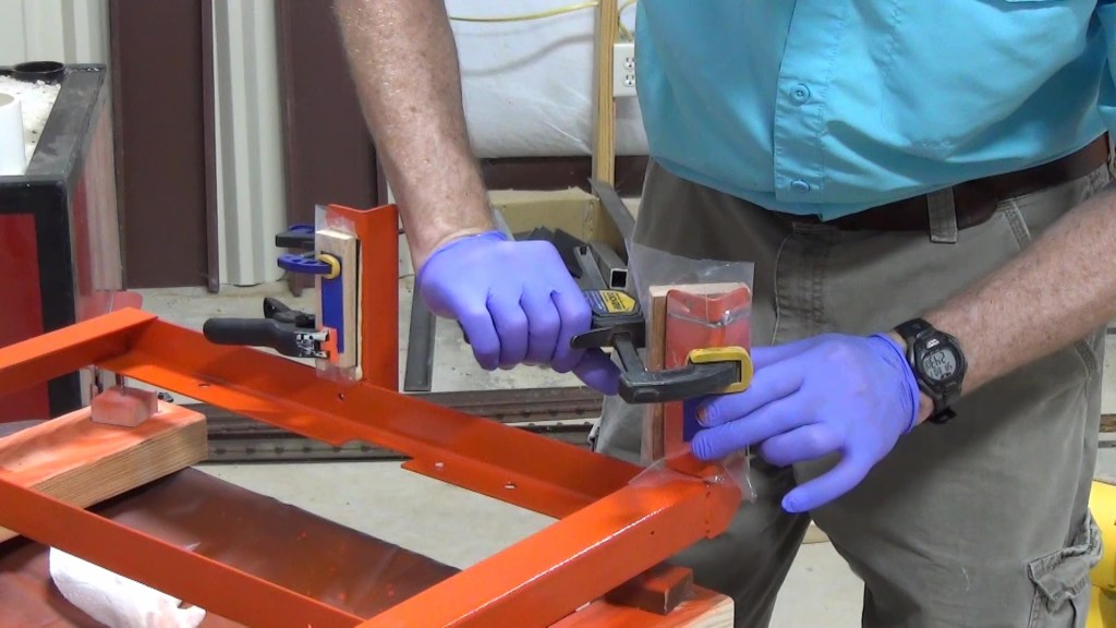
With that problem solved, it was time to glue the rubber gripping pads on the clamp plates. Some scraps of rubber pond liner I had were perfect for this, but you could also use pieces of an innertube . Gorilla Glue is a good choice for gluing the pieces on. At little goes a long way! I used the piece I had cut off the frame to press it down and then clamped it to the welding table to cure.
I did the same to the frame scabbard supports, only this time I wrapped the holding pieces in plastic so that excess glue didn’t stick to them.


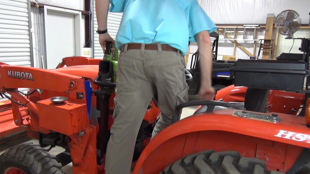
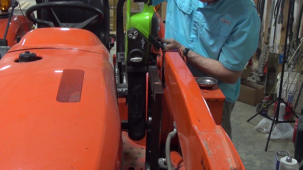
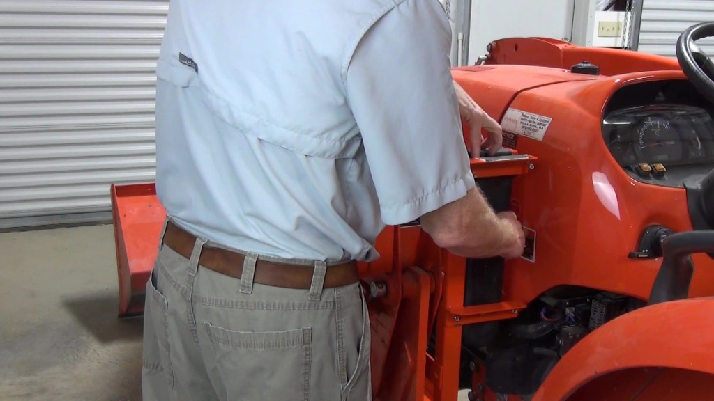
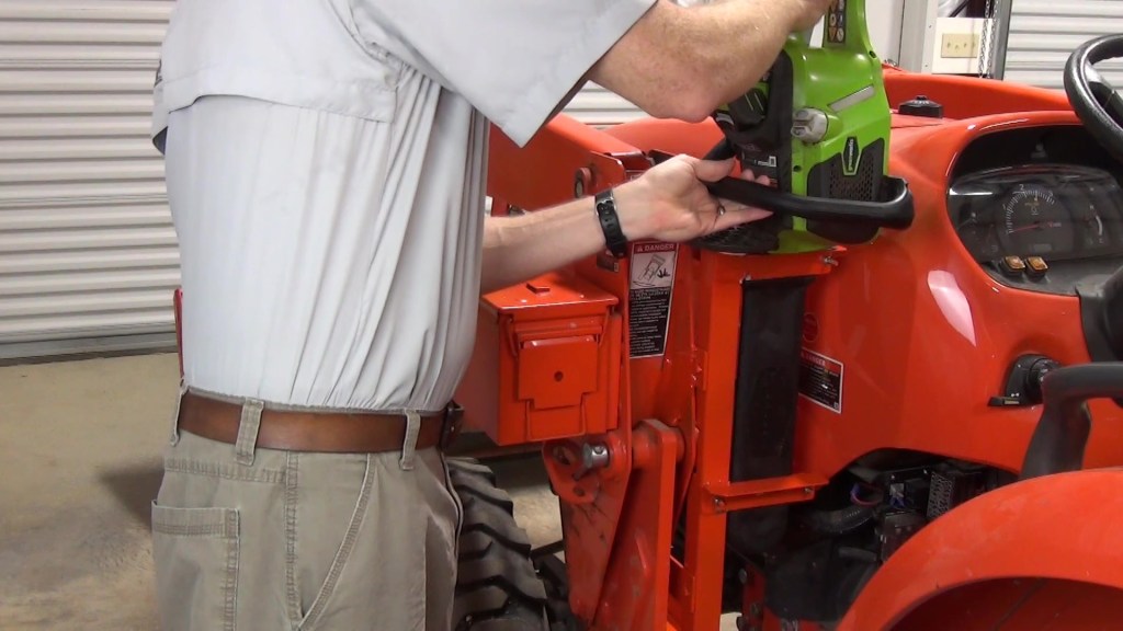
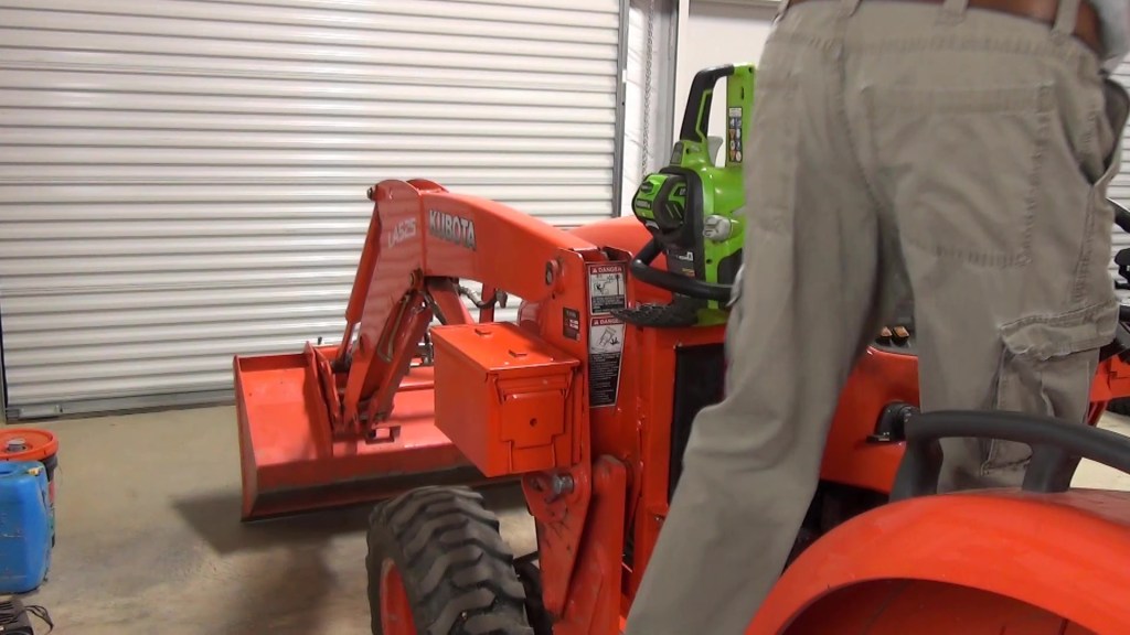
With the frame back on the tractor, it was time for a dry run. I tightened the ¼” nylock nuts onto the clamp plate screws to draw them snug, but not too tight. I put the chainsaw in the scabbard and got on the tractor. It didn’t get in the way of getting on or off the tractor which was great!
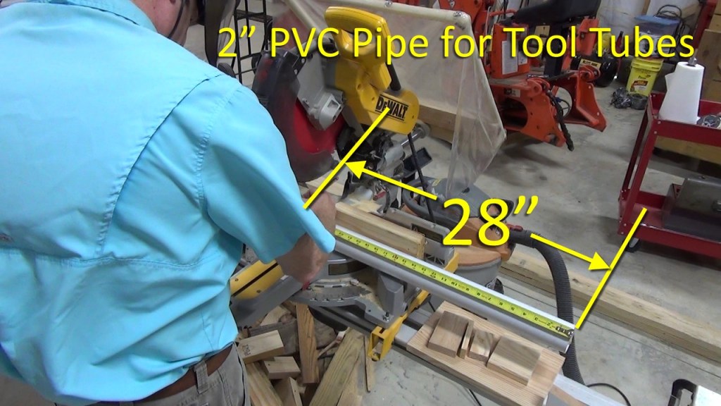
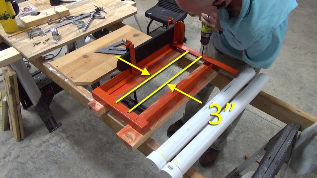
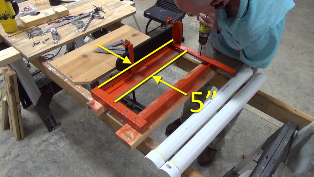
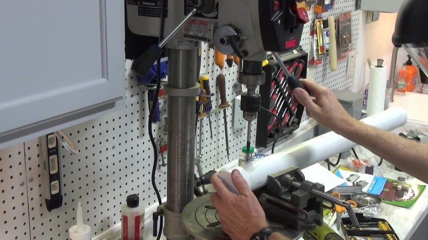
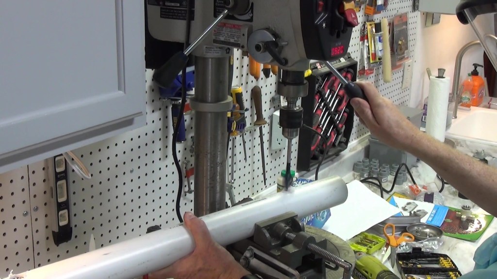
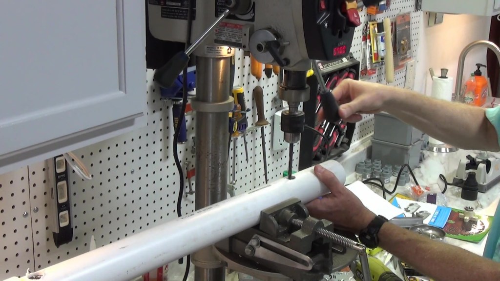
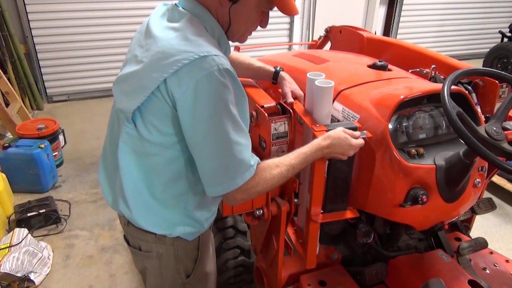
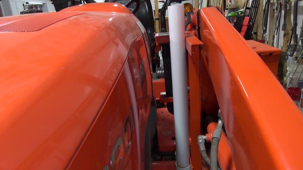
Next, I cut two sections of PVC pipe, 28″ long. Then I drilled and tap ¼” by 20 threaded holes 3″ apart with the first set of holes 5″ from the rear vertical support. Also these holes are 20 ¾” apart from top to bottom. Note that I glued end caps on the tool tubes and drilled 3/8″ drain holes in each.
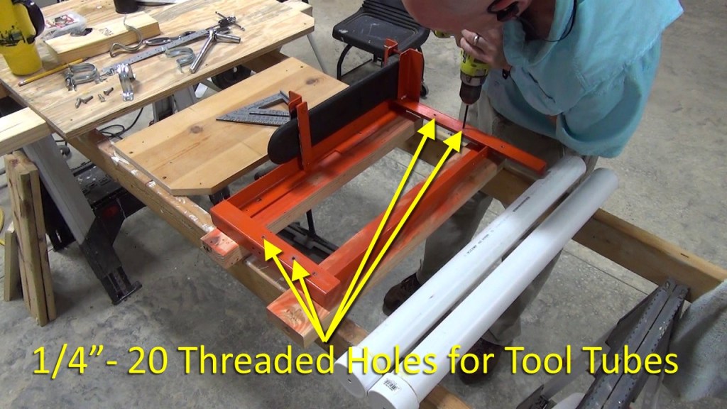


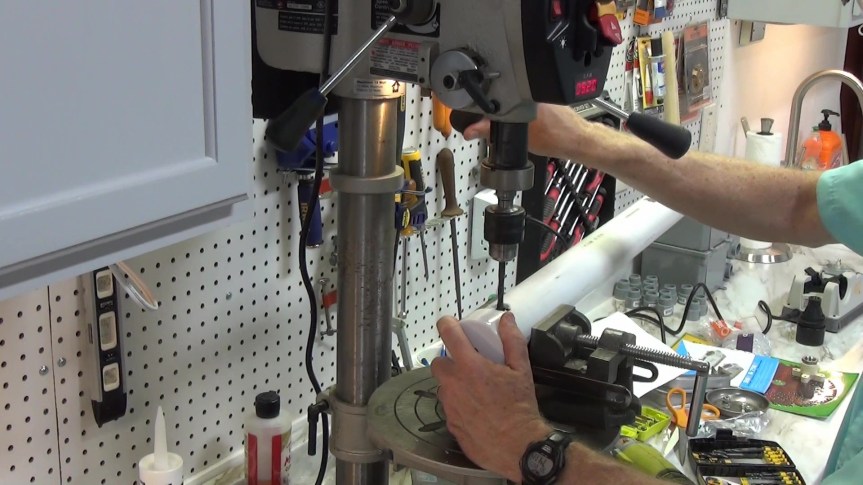
Then I drilled two pilot holes 20 ¾” apart, starting 5″ from the top on each tool tube. Followed by 7/8″ holes to allow a socket to pass through. Then I drilled 5/16″ holes through the opposite side of the tubes.


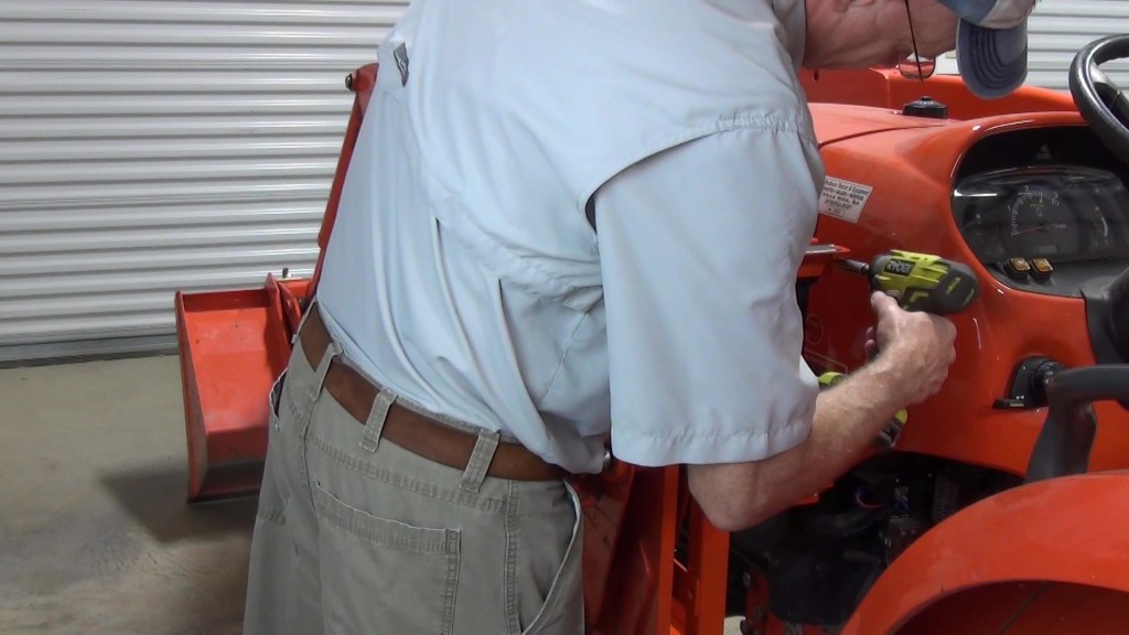
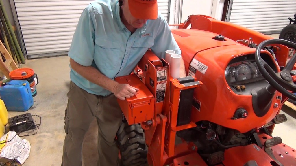
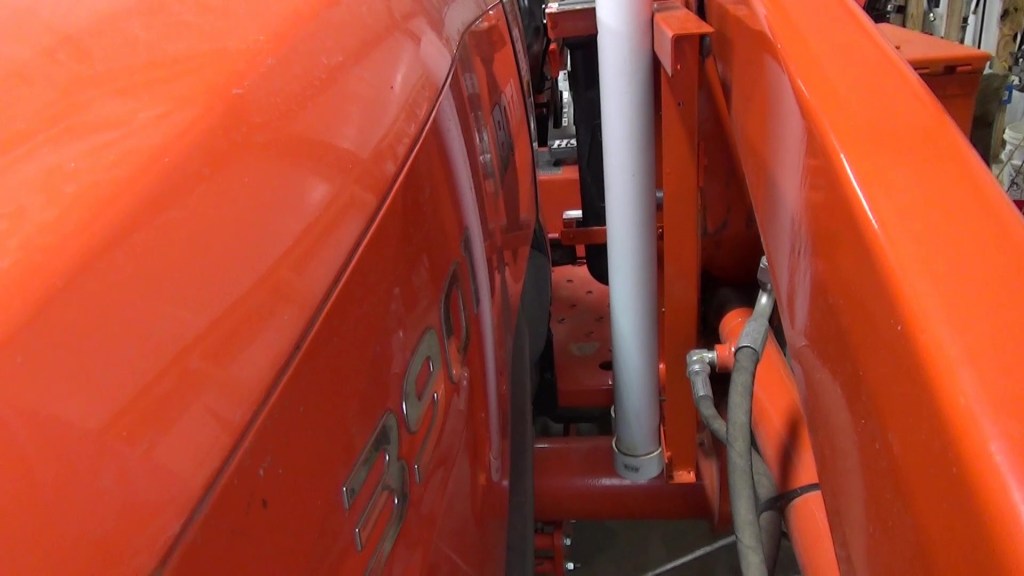
I attached the tubes with 1″ ¼” bolts and lock washers. Again, I was just using what I had on hand. Half inch long ¼” screws would have been fine too.
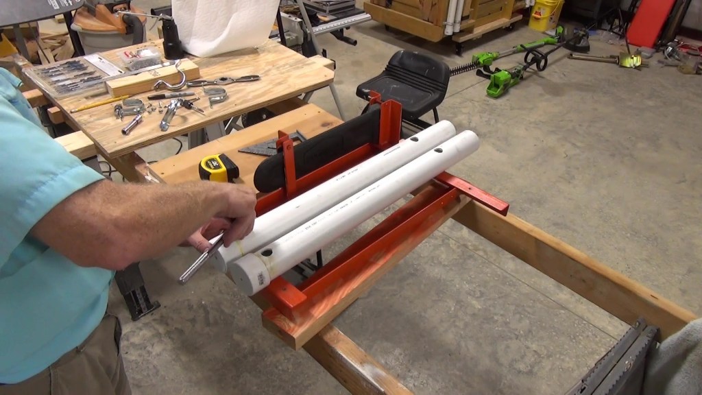
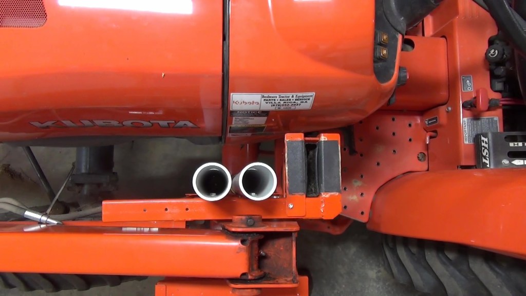
Finally, I mounted the finished product to the FEL using stainless steel 5/16″ nylock nuts to secure it to the mounting bars.
The bottom line is if you build something similar, keep in mind the space you have available and maintain safe clearances from any moving parts like your wheels or loader arms.

One thought on “Tractor FEL Mounted Chainsaw Scabbard and Tool Holder”
Comments are closed.