
If you want to add electrical accessories to your tractor beyond what the work light connection can handle, then you need to add an extra fuse box to your tractor. Here is how I added one to my Kubota.
Here’s a list of the materials I ordered from Amazon:
- 6 Way Blade Fuse Box for Automotive Blade Fuses, 100A, with LED Indicators
- MICTUNING Heavy Duty 14AWG 300W 2-Circuit Led Light Bar Wiring Harness
- 14 Gauge 50’FT Wire Copper Clad Single Conductor 6 Primary Colors
- 3/8″ Split Nylon Wire Loom Flexible Conduit – 25 Feet
- UV Resistant Tie Wraps, 14″ Long, 100-Pack
- Waterproof 12 VoltPower Outlet
I wanted my extra fuse box to be mounted near the factory fuse box, but there wasn’t a convenient place, so I had to get creative.
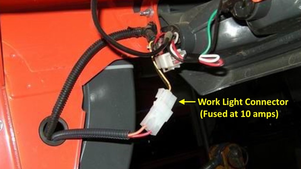
Like with my video on the ROPS mounted LED lights, it begins with the Work Light Connection. If your tractor has one, it is usually located under the left or right rear fender. On the Kubota L Series tractors it is located under the left rear fender. This connection is hot only when the ignition key switch is on or the tractor is running.
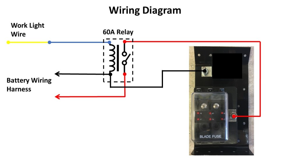
Let’s start with a diagram of how I wired in the fuse box and then I’ll get into the specifics of hardware and installation. The Diagram is below:


When the work light connection is hot, the 60A relay is energized and allows power to flow from the battery to the fuse box. So why is a 60 amp relay being fed by a 30 amp fuse? Well first, it’s because those parts are what came with the harness kit I mentioned in the ROPS LED Lights video. However, in my opinion, over sizing the relay will insure a long life for the relay contacts. I did not use the wiring harness as is but instead I cut up the cabling and used the pieces for my design.
By the way, the wiring harness uses 14-gauge wire. If you think your accessories will exceed the 30 amps of the inline fuse, you should use a heavier gauge wire for the harness from the battery to the relay and fuse box.
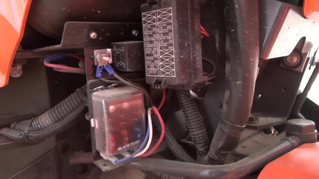
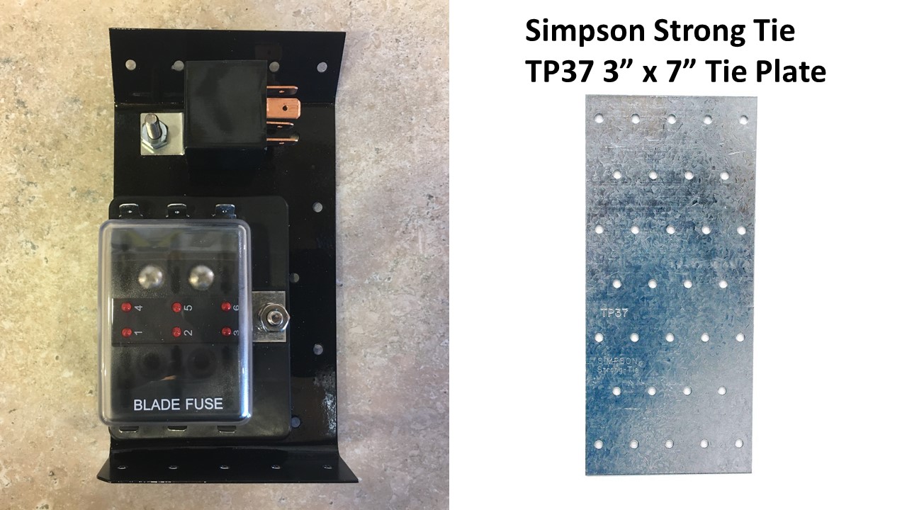
Now about that fuse box. The one I chose is a 6-way blade fuse box from Amazon. It has a 100 amp total capacity and a 30 amp max per circuit. A clear plastic cover protects the fuses from evil. It has a #10-32 stud for connecting power. Blown fuse indicators for each circuit make it easy to figuring out which fuse is blown.
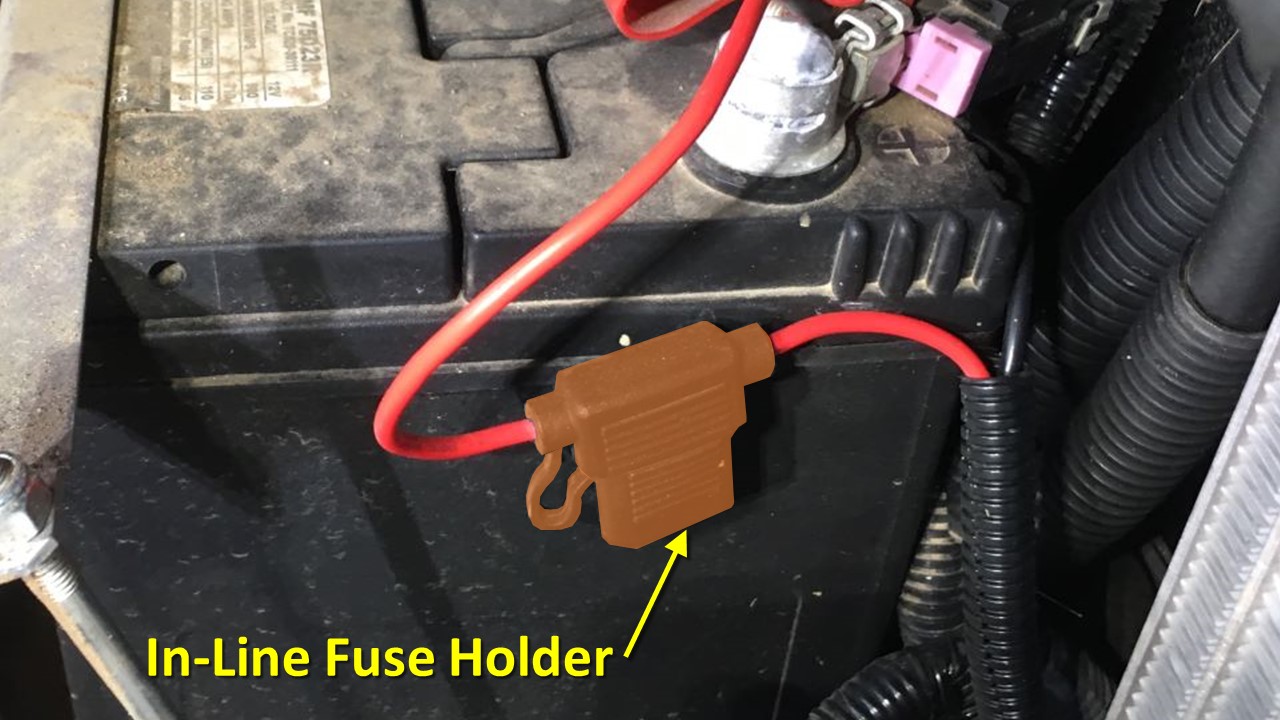
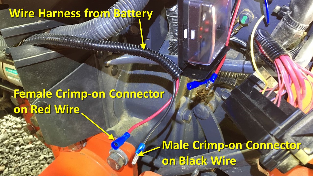
Starting from the battery, the wiring harness black wire connects to the negative post with an eyelet connector. Likewise, the red wire connects to the battery’s positive post.
Notice the in-line fuse holder on the positive wire. This is where the 30-amp fuse goes.
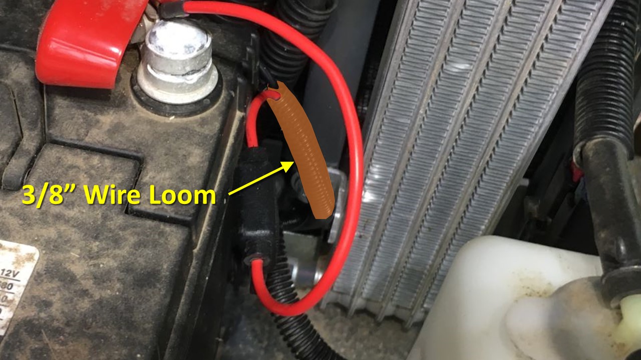
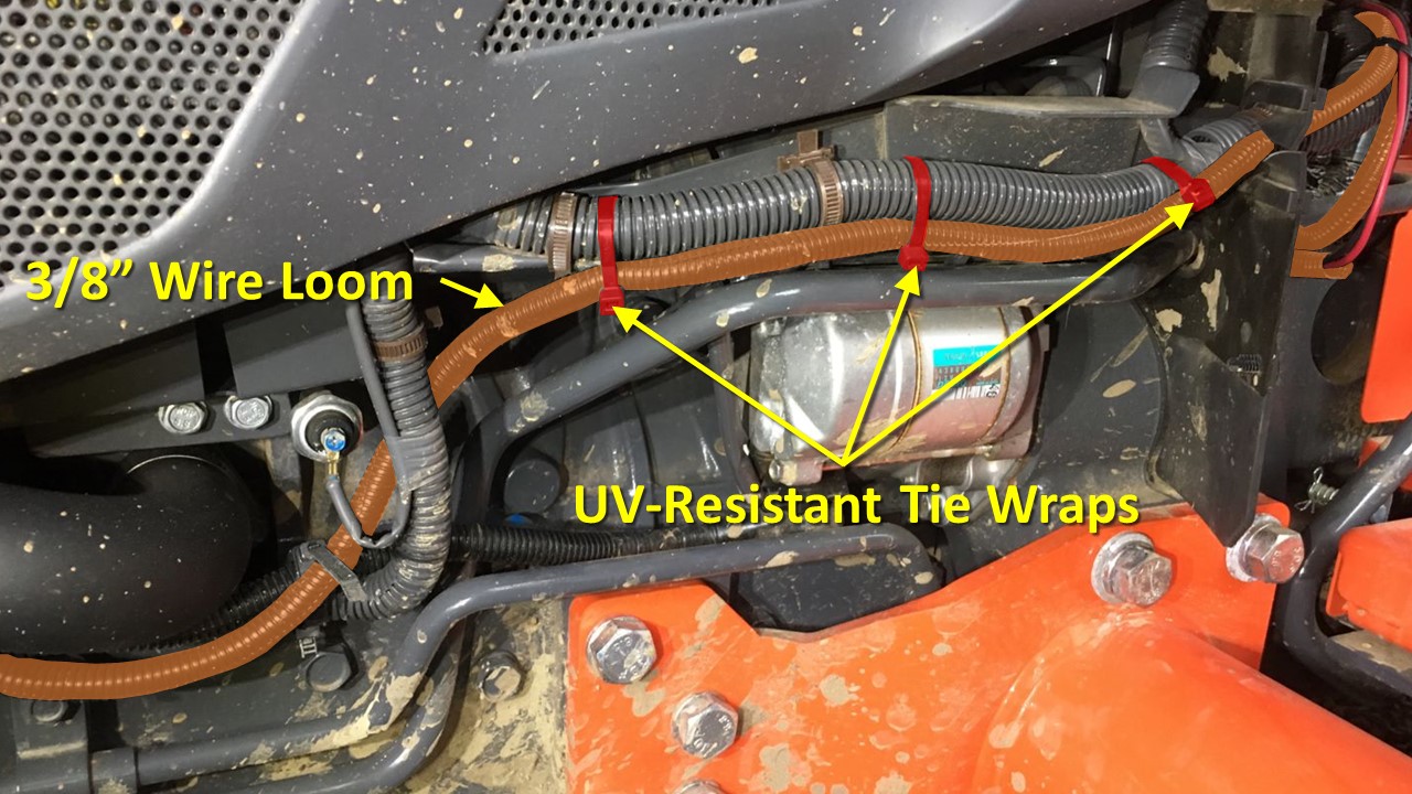
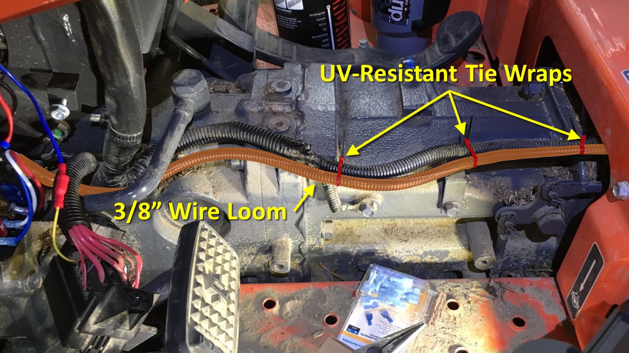
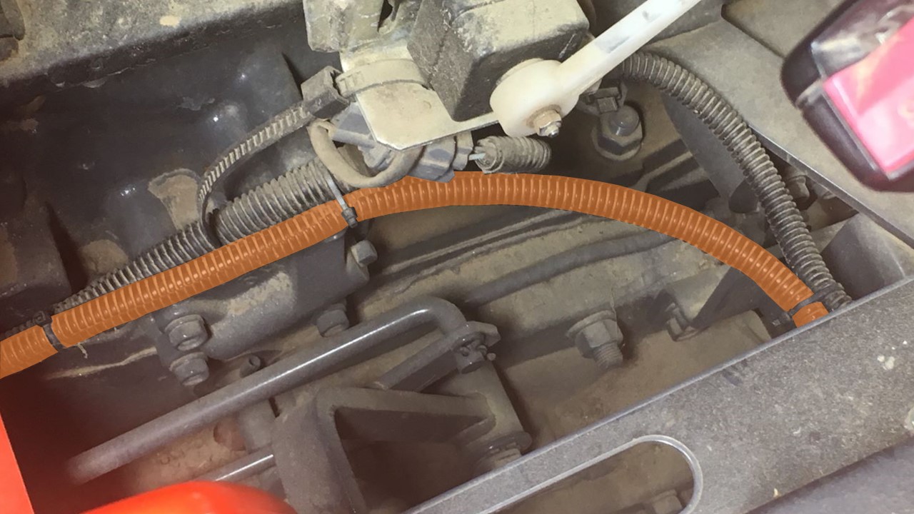
Wires are protected in 3/8” wire loom as they leave the battery compartment on their way to the fuse box. I keep the harness and wire loom as far away from hot surfaces and possible, tie wrapping it to existing wire loom whenever possible.
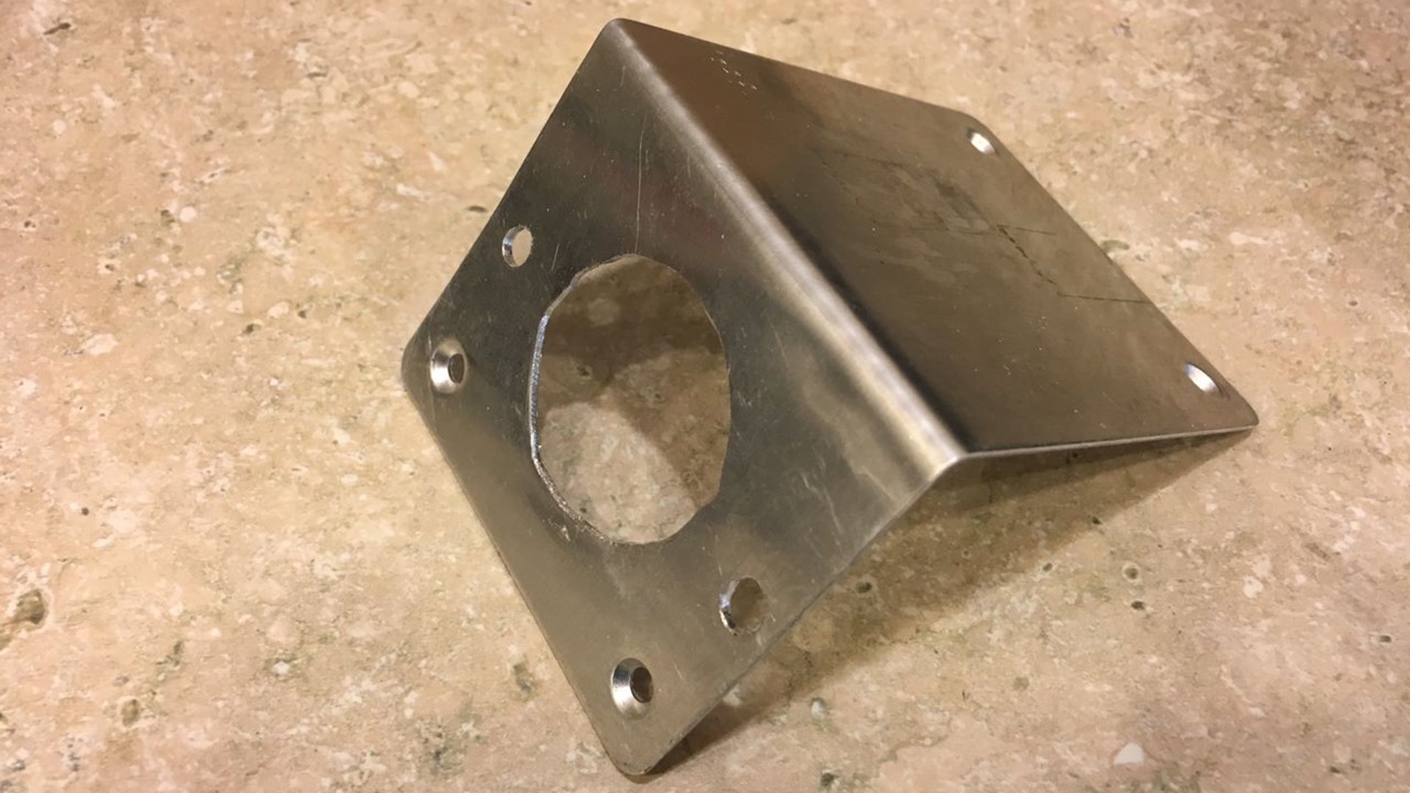
I mounted the fuse box and relay on a metal plate that I made from a 3” by 7” Simpson Tie Plate, which is normally used in construction to tie lumber together.
I measure the angle on that plate on the tractor so I could bend the first inch of the tie plate to the correct angle. I also bent 1 inch of other end 90 degrees.
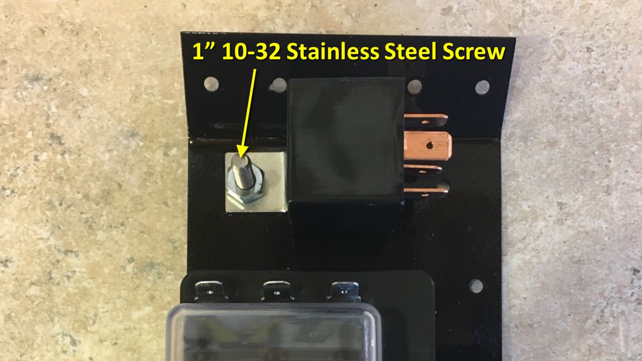
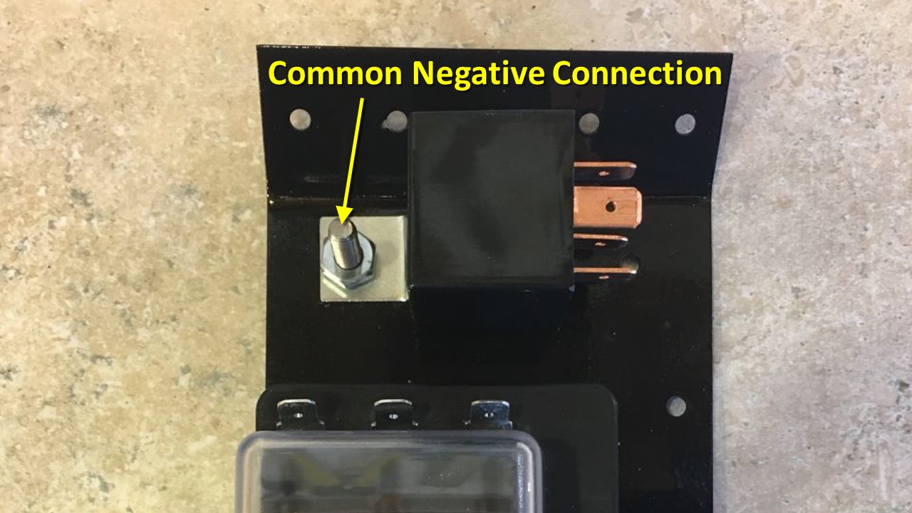
Then I primed it and painted it gloss black. Oh, and I also clipped and filed this corner to get rid of the sharp edge. The relay is mounted to the top of the plate with a 1” #10-32 stainless steel screw, lock washer and nut, using one of the existing holes in the plate. This screw also serves as the common connection point for the negative wires.
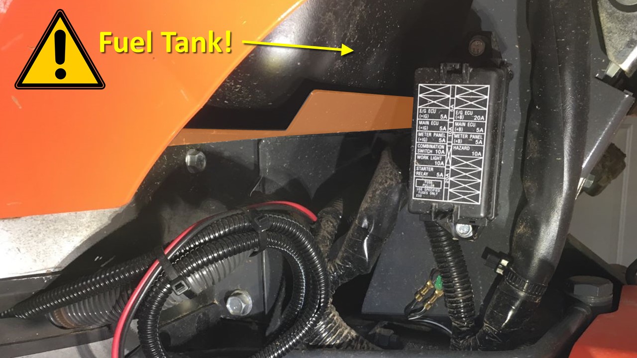
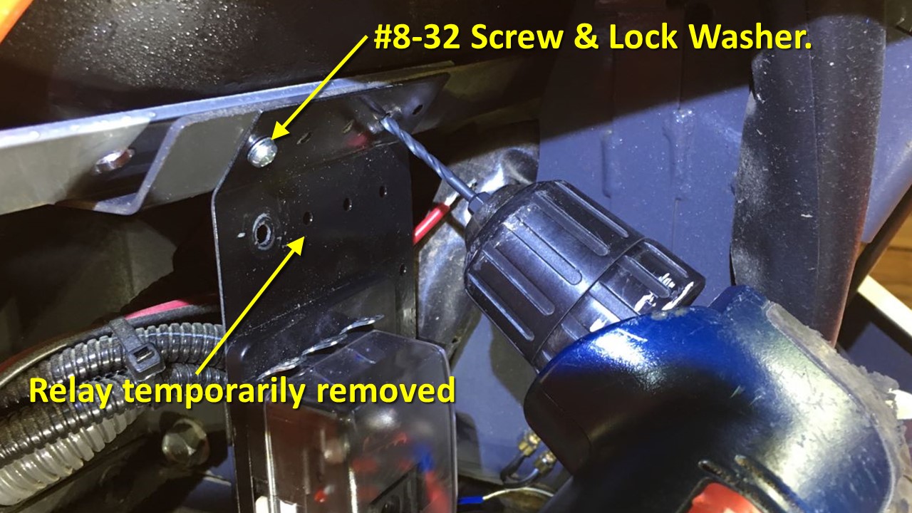
Now comes the tricky part I mentioned. This plate I’m about to mount the fuse box to happens to be right below the fuel tank. A plastic fuel tank, at that! I’m about to drill holes in the plate and it has been my experience that fuel tanks DO NOT like to be drilled into so I have to make sure that doesn’t happen.
First I need to get the factory fuse box out of the way by removing the two bolts that attach it to the frame.
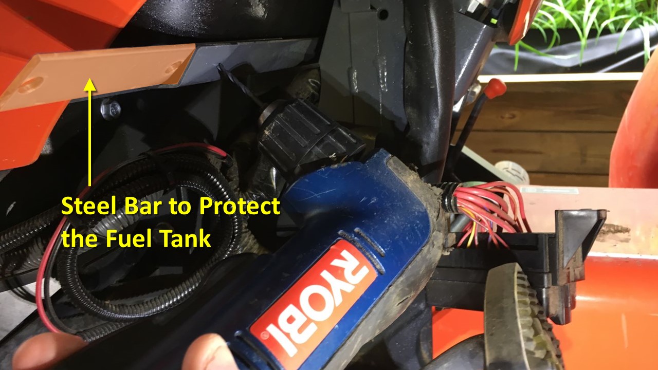
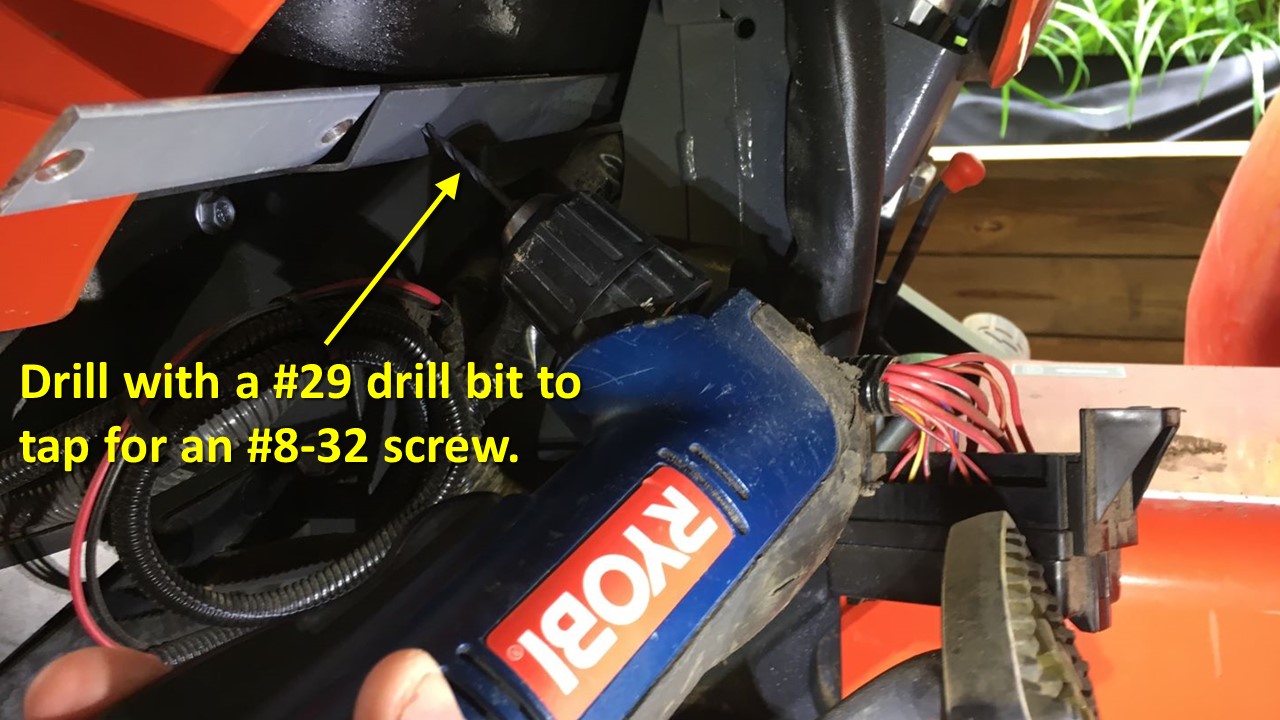
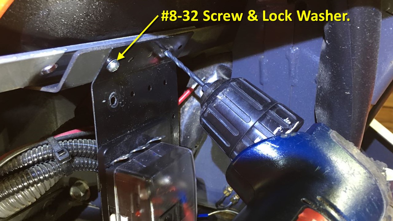
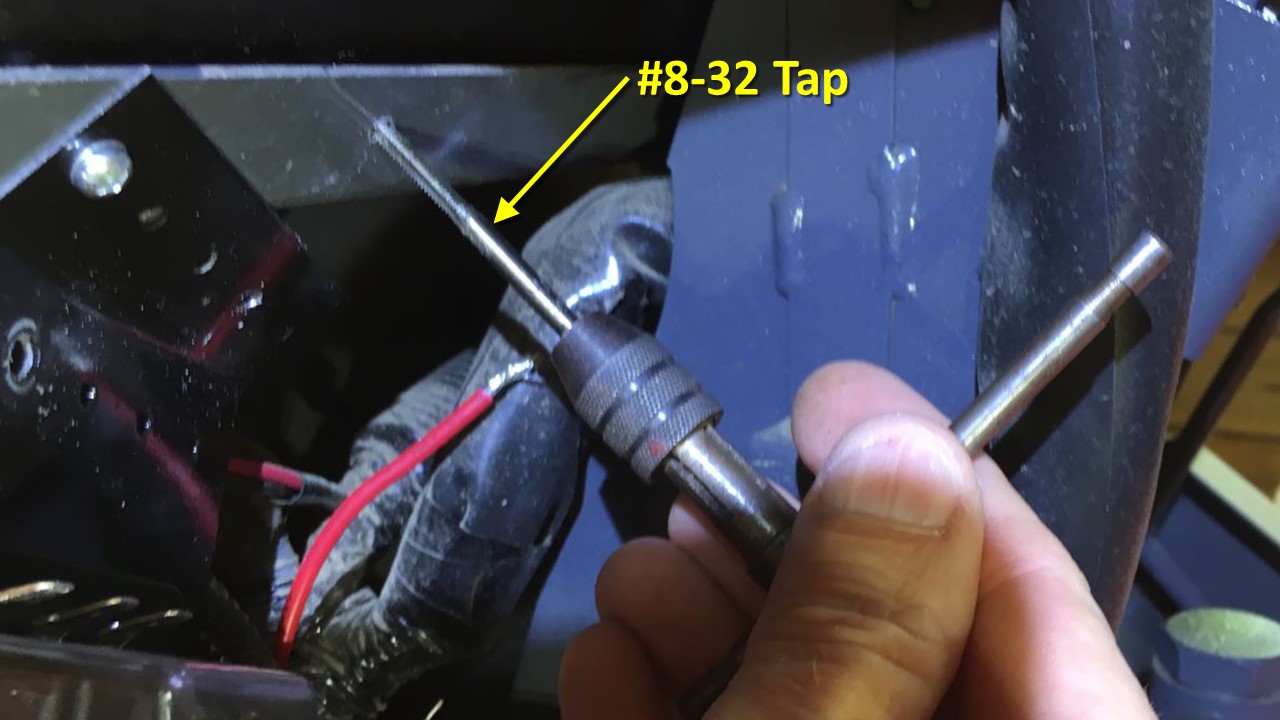
Then I place a piece of steel flat bar between the mounting plate and fuel tank to protect the fuel tank while I am drilling. I used a number #29 drill bit so I can tap the hole for an #8-32 screw. Just between you and me, you could use an 1/8” drill bit in a pinch.
Now it’s time to wire all this up.
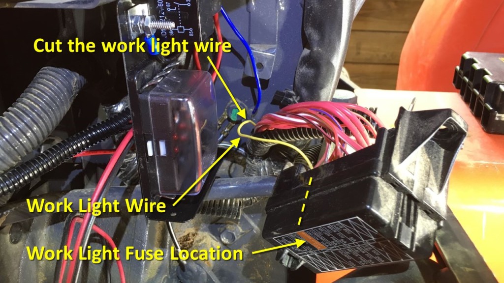
Now it’s time to wire all this up. First, I peel back the wire loom of the factory fuse box to locate the work light wire leaving the fuse box. In the case of my tractor it is a yellow wire. Your tractor’s work light wire color maybe different so make sure you have the right wire! You can verify it by noticing where the work light fuse is in the fuse box and look for the wire directly to the back of it.
Now take a deep breath and cut the work light wire two or 3 inches back from the fuse box, then tuck the rest of the fuse box wires back into the wire loom, leaving the work light wire out.
I removed the in-line 30-amp fuse from the battery wiring harness, then cut the excess wire and wire loom from the harness, leaving enough to comfortably wire things up. Next, I stripped the ends of the wires and crimped on inline wire connectors, putting the female connector on the positive connector and the male connector on the black wire. I always put female connectors on positive wires from the battery to reduce the chance of a short between the wire and the tractor chassis, which is negative.
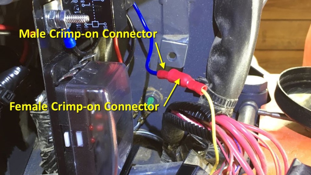
Then I stripped the wires on the relay plug going to the relay and crimped a male connector on to one of the red relay contact wires and a female connector on the black wire. After that, I connected red to red and black to black.
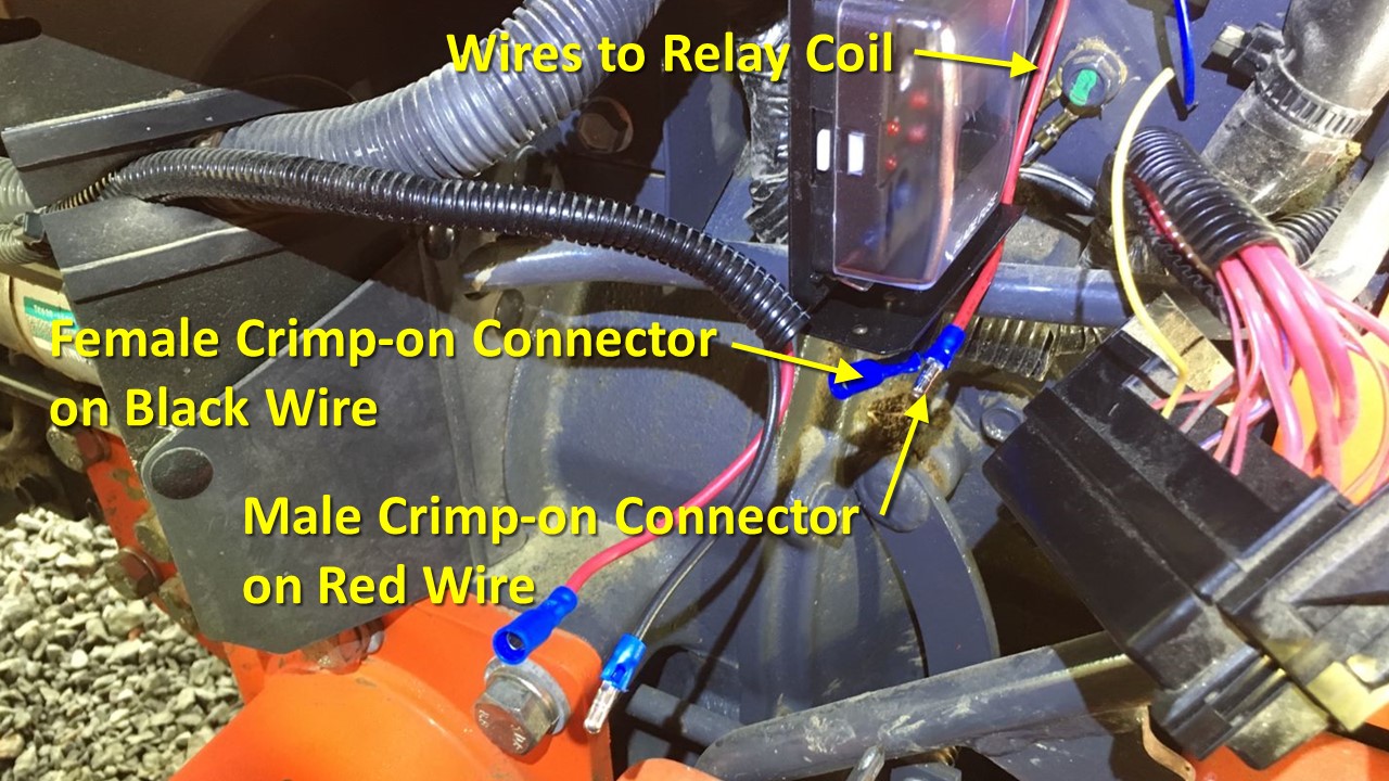
Next, I crimped a female connector on to the work light wire coming from the factory fuse box and the crimped a male connector on to the wire going to one side of the relay coil. This wire happens to be blue in the harness I used but it could be different for a different brand of harness. Just pay attention to the diagram on the relay and the color of the wires coming from the relay plug.
The diagram below show how all this is hooked up:
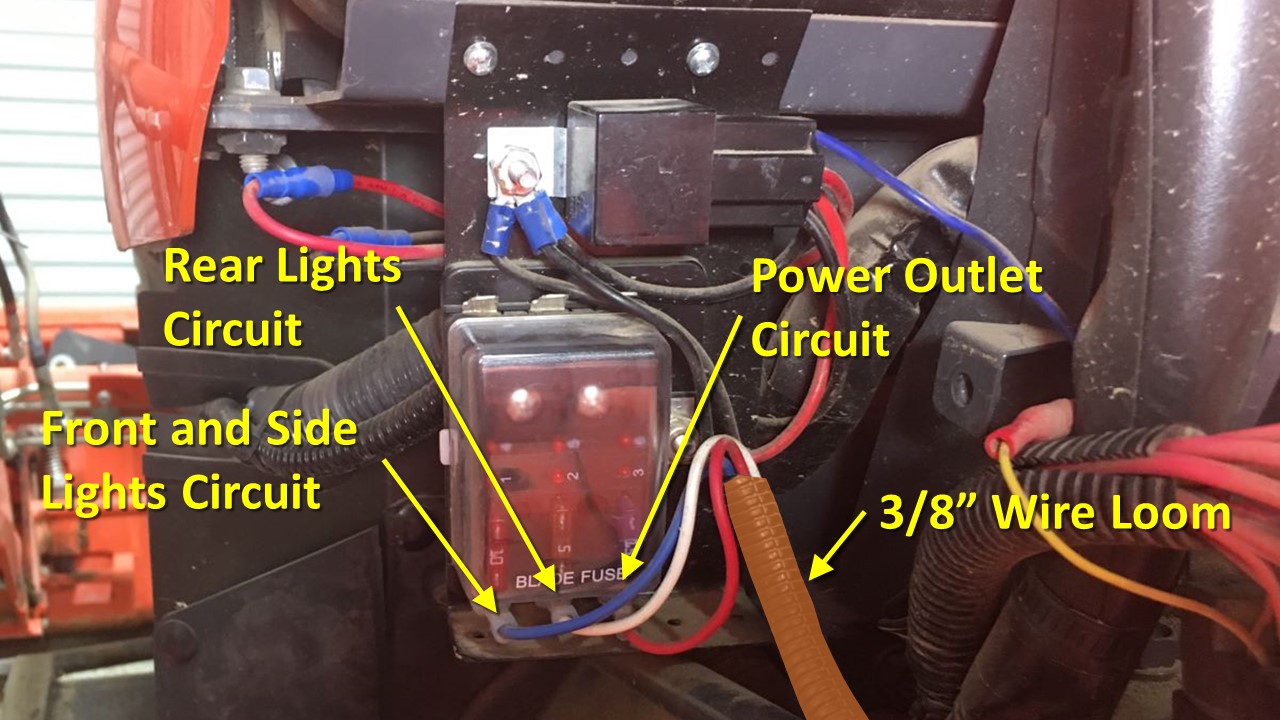
The front and side light circuit is fused at 10 amps. The rear lights are fused at 5 amps and the power outlet is fused at 15 amps, which is what it is rated for. All the wires connect to the fuse box with insulated crimp-on female spade terminals.

The circuits leave the fuse box in 3/8” wire loom and heads toward the back of the tractor attached to an existing wire loom with UV resistant tie wraps.
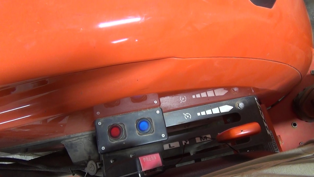
The wires arrive at my lights switch box from which they branch off to lights and to the power outlet. The details of the lights wiring are covered in my ROPS LED lights video, so I’ll just cover the power outlet.
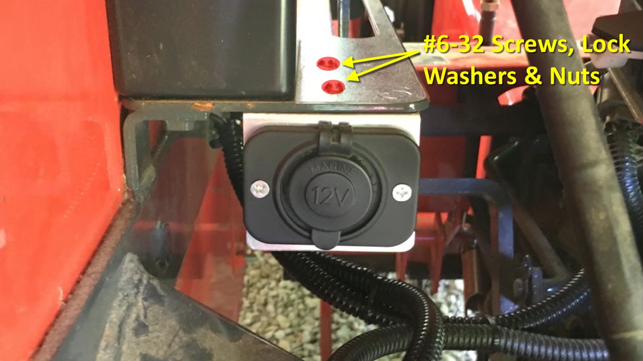
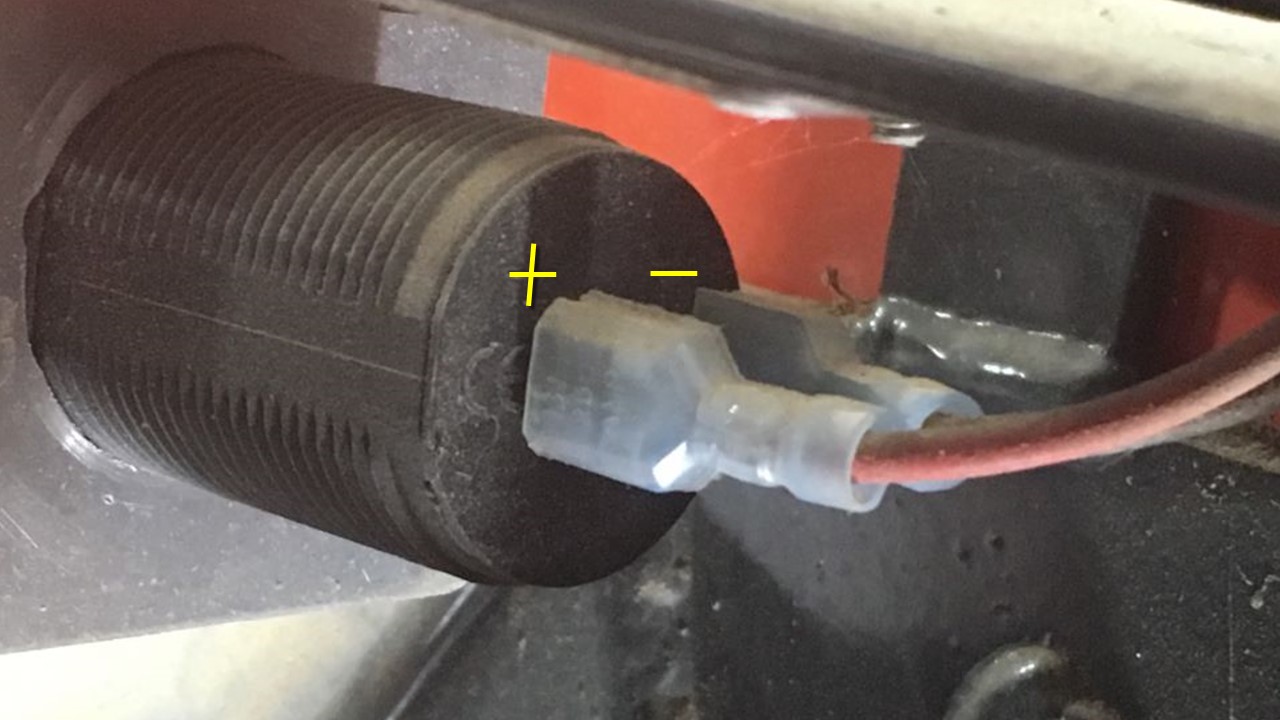
The outlet is mounted just below the switch box using two #6-32 screws, lock washers and nuts.
I made the mounting plate for the outlet from the metal cover plate from a small electronics enclosure I had lying around. Make sure you get the polarity correct when connecting the wiring to the outlet!
Note: Links to Amazon products are Amazon Associate links that won’t cost you any extra, but will help support my efforts with a small commission on qualified products. Thanks for your support!
